I. Basic Definitions and Core Differences of Pressure Units
In the industrial pressure measurement system, PSI, PSIA, and PSIG are three of the most easily confused yet crucial units. Their core differences stem from different pressure references:
- PSI (Pounds per Square Inch): A basic pressure unit defined as the force in pounds applied per square inch of area. It is widely used for pressure labeling in the imperial system (e.g., 1 PSI = 6894.76 Pa).
- PSIA (Pounds per Square Inch Absolute): A pressure value referenced to absolute vacuum, including atmospheric pressure (standard atmospheric pressure ≈ 14.696 PSI). Specifically, PSIA = Gauge Pressure + Atmospheric Pressure.
- PSIG (Pounds per Square Inch Gauge): A relative pressure referenced to ambient atmospheric pressure, excluding atmospheric pressure itself. That is, PSIG = Absolute Pressure – Atmospheric Pressure.
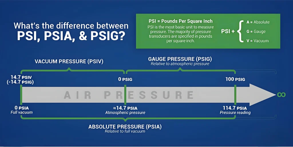
Core Formulas:\(\begin{cases} \text{PSIA} = \text{PSIG} + \text{Atmospheric Pressure (standard value 14.696 PSI)} \\ 1 \, \text{PSI} = 0.06895 \, \text{atm} = 6894.76 \, \text{Pa} \end{cases}\)
II. In-Depth Analysis of Application Scenarios in the Valve Industry
(A) PSI: The Universal “Language” of Industrial Pressure
As the most fundamental pressure unit, PSI is applied throughout the entire process in the valve field:
- Selection Basis: The rated working pressure marked on valve nameplates (e.g., “MAX 150 PSI” on a DN50 ball valve) and the design pressure of pipeline systems both use PSI as the unit.
- Test Standards: Pressure indicators for hydrostatic tests and pneumatic tests (e.g., API 598 standard requires the shell test pressure to be 1.5 times the nominal pressure in PSI).
- Civil Extensions: The basis for pressure value conversion in scenarios such as household pipeline water pressure (recommended 40-60 PSI) and fire protection system pressure monitoring.
(B) PSIA: The Core Parameter for Vacuum Systems
Valve design involving vacuum environments must rely on precise PSIA measurement:
- Vacuum Valve Selection: Sealing performance parameters of vacuum stop valves and vacuum butterfly valves (e.g., leakage rate ≤ 1×10⁻⁹ mbar·L/s corresponds to approximately 0.15 PSIA).
- Process Control: Pressure control for equipment such as vacuum distillation columns and freeze dryers (typical working range 10-100 PSIA), which requires real-time monitoring via absolute pressure sensors.
- Core Advantage: Eliminating the interference of atmospheric pressure to directly reflect the true pressure state of the system (e.g., when atmospheric pressure at 1000 meters altitude is approximately 14.1 PSI, PSIA = PSIG + 14.1).
(C) PSIG: The “Standard Interface” for Industrial Gauge Pressure Measurement
More than 90% of industrial pressure gauges default to displaying PSIG because it aligns with operators’ intuitive understanding of “relative pressure”:
- Real-Time Monitoring: Direct adjustment of pressures in hydraulic systems (e.g., 3000 PSIG for injection molding machine hydraulic valves) and pneumatic valve actuators (commonly 60-100 PSIG) through gauge pressure.
- Safety Protection: Setting the trip pressure of safety valves (e.g., triggering pressure relief when PSIG ≥ 150 in boiler steam pipelines), with pressure switch 联动 logic using PSIG as the threshold.
- International Standards: Valve pressure classes in ASME B16.34 (Class 150 corresponds to a maximum working pressure of 285 PSIG at 100℃), directly using gauge pressure for labeling.
III. Key Conversion Relationships and Engineering Calculations
(A) Unit Conversion Under Atmospheric Pressure Influence
| Pressure Type | Reference | Relationship with PSI | Typical Application Scenarios |
|---|---|---|---|
| Absolute Pressure | Vacuum | PSIA = PSIG + P<sub>atm</sub> | Vacuum systems, meteorological monitoring |
| Gauge Pressure | Atmospheric Pressure | PSIG = PSIA – P<sub>atm</sub> | Industrial pressure gauges, hydraulic systems |
| Standard Atmospheric Pressure | Sea Level | 1 atm = 14.696 PSI = 101.325 kPa | Pressure unit reference |
Engineering Example: If a pressure gauge in a chemical plant pipeline shows 30 PSIG and the local atmospheric pressure is 14.2 PSI, the absolute pressure is 30 + 14.2 = 44.2 PSIA. To convert to kPa, first calculate the PSI-to-kPa value (30 × 6.895 = 206.85 kPa), then add the atmospheric pressure (101.325 kPa), resulting in a total pressure of 308.175 kPa.
(B) Comparison of Vacuum Degree Representation Methods
| Vacuum Description | Pressure Range (PSIA) | Corresponding PSIG | Valve Type |
|---|---|---|---|
| Low Vacuum | 14.696~1 | 0~-13.696 | Valves for water-ring vacuum pumps |
| High Vacuum | 1~10⁻³ | -13.696~-14.693 | Metal bellows-sealed valves |
| Ultrahigh Vacuum | <10⁻³ | ≈-14.696 | Magnetron sputtering vacuum valves |
IV. Typical Cases and Error Avoidance
Case 1: Leakage Caused by Confusing PSIA/PSIG in Vacuum Valve Selection
Background: A pharmaceutical factory selected a ball valve labeled “10 PSI sealing pressure” for its freeze dryer, but the vacuum degree failed to meet the standard during trial operation (target 1 PSIA, actual 10 PSIG). Analysis: Mistakenly taking gauge pressure PSIG as absolute pressure PSIA. 10 PSIG corresponds to an absolute pressure of 10 + 14.696 = 24.696 PSIA, far higher than the target value. Solutions:
- Specify that PSIA parameters must be used for vacuum systems, and replace the valve with a vacuum-specific ball valve labeled “1 PSIA maximum leakage pressure”.
- Install an absolute pressure transmitter to display PSIA values in real time and link them to valve control.
Case 2: Pipeline Bursting Due to Misinterpreting PSI in Hydrostatic Testing
Background: A municipal project adjusted a pressure reducing valve according to “60 PSI” during testing, but the pipeline burst after water supply (design pressure 80 PSI). Analysis: Failing to distinguish whether PSI represented gauge or absolute pressure. With a local atmospheric pressure of 14.5 PSI, the actual system pressure was 60 + 14.5 = 74.5 PSIA (approximately 514 kPa), exceeding the pipeline’s nominal 60 PSIG (413.7 kPa). Solutions:
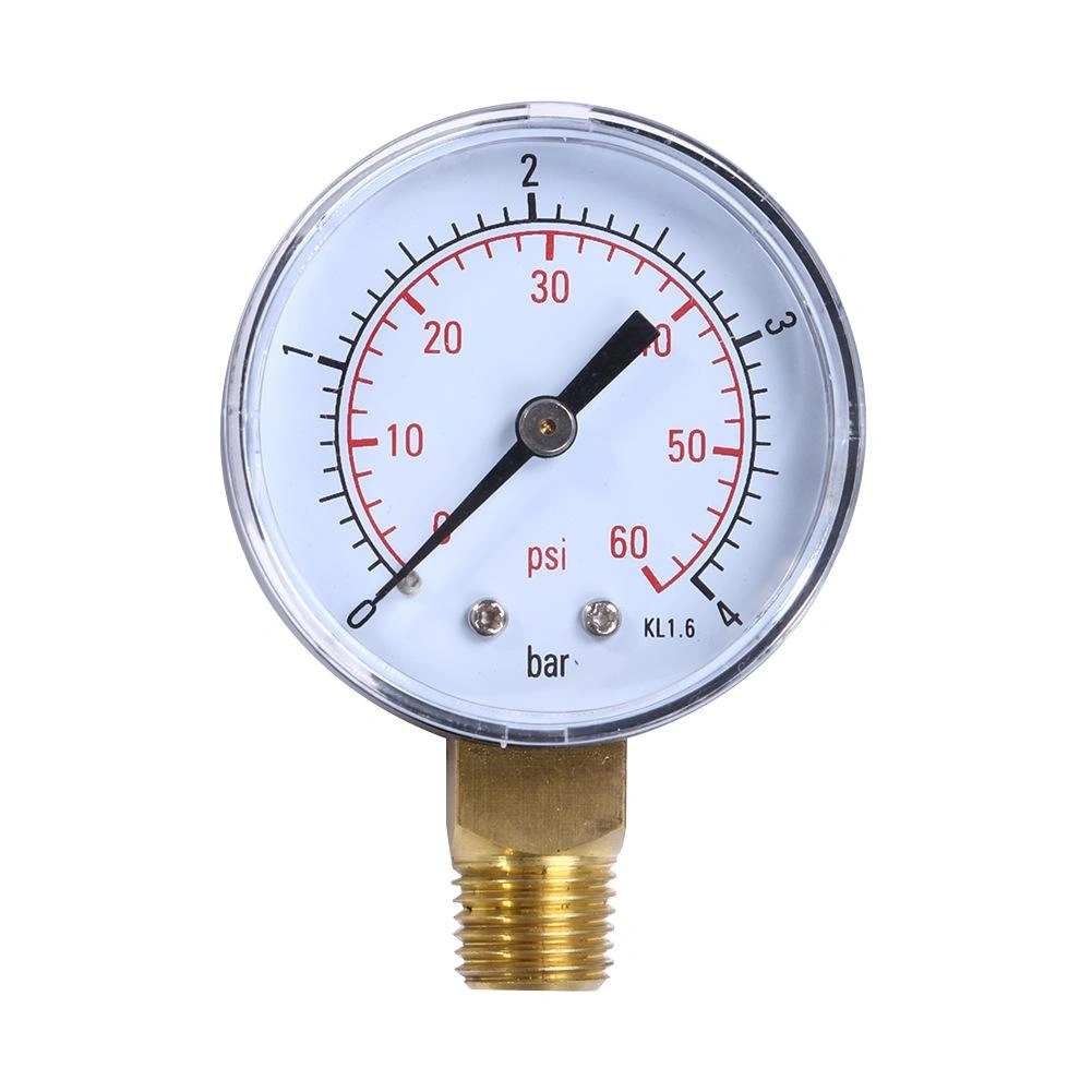
- Clearly label pressure parameters with units (e.g., “60 PSIG” or “60 PSIA”).
- Confirm the reference pressure before debugging and use intelligent pressure gauges with unit identification (e.g., displaying “60 PSIG (Gauge)”).
V. Industry Standards and Instrument Selection Guidelines
(A) Key Provisions of International Standards
- ASME B16.5: The flange pressure class Class 300 corresponds to a maximum gauge pressure of 600 PSIG at 260℃, explicitly using PSIG as the gauge pressure unit.
- ISO 5167: In flow measurement standards, the range corresponding to the output signal (4-20mA) of differential pressure transmitters must be labeled with PSIG or PSIA.
- API 6D: Valve specifications require pressure test reports to record both PSIG values and atmospheric pressure values for easy conversion to PSIA.
(B) Instrument Selection Key Points
| Instrument Type | Measurement Type | Output Unit | Typical Model | Application Scenario |
|---|---|---|---|---|
| Ordinary Pressure Gauge | Gauge Pressure (PSIG) | PSIG/bar | Dwyer DPI620 | Conventional industrial pipelines |
| Absolute Pressure Transmitter | Absolute Pressure (PSIA) | PSIA/kPa | Rosemount 3051 | Vacuum systems, meteorological equipment |
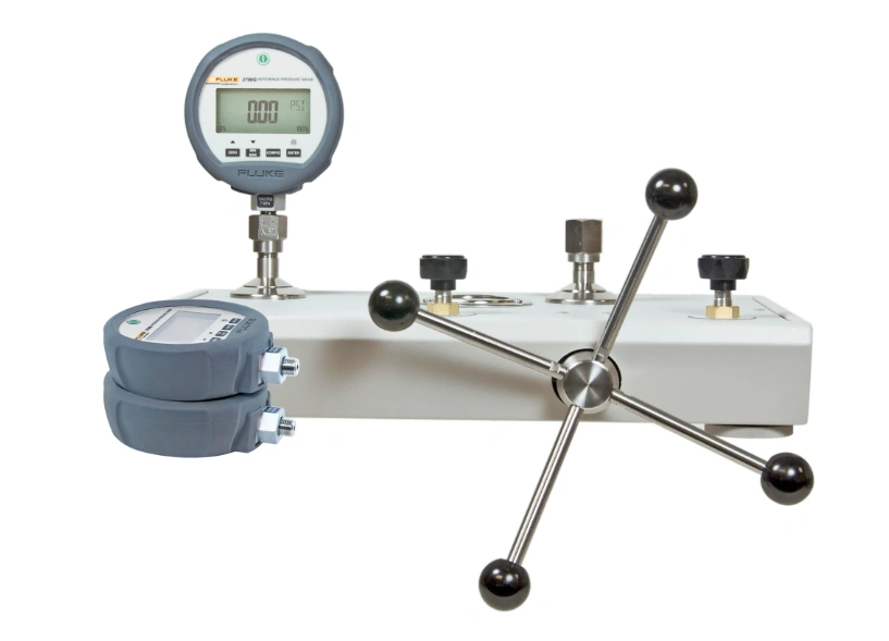
| Intelligent Pressure Calibrator | Dual Mode | PSIG/PSIA | Fluke 729 | Calibration and debugging |
VI. Core Principles for Efficient Application
- Clear Labeling: Valve technical documents and pressure gauge dials must clearly mark units (e.g., “PSIG (G)”, “PSIA (A)”).
- Scenario Priority: Use PSIA for vacuum environments, PSIG for conventional industries, and PSI for basic pressure labeling.
- Dynamic Conversion: For every 1000 meters increase in altitude, atmospheric pressure decreases by approximately 1 PSI; real-time correction as PSIA = PSIG + measured atmospheric pressure.
- Dual Parameter Monitoring: Display both PSIG and PSIA in critical systems (e.g., DCS interface showing “Gauge: 30 PSI” and “Absolute: 44.7 PSIA” simultaneously).
The correct application of PSI, PSIA, and PSIG is a core technical support for valve selection, system design, and safe operation. By clarifying pressure references, mastering conversion logic, and following industry standards, we can effectively avoid selection errors, measurement deviations, and safety hazards caused by unit confusion. In the era of industrial intelligence, it is recommended to integrate IoT sensors and digital systems to achieve real-time multi-unit display and intelligent conversion of pressure parameters, fundamentally enhancing the reliability and efficiency of valve systems.


