Executive Summary
Midstream natural gas infrastructure continues rapid global expansion throughout 2026, with mid‑market Google search analytics showing a 34% year‑over‑year increase in engineering queries for buried fully welded trunnion ball valves, driven by large‑scale cross‑border transmission projects, pipeline integrity upgrade programmes, and tightening regulatory requirements for fugitive emissions and underground equipment safety. Long‑distance natural gas transmission pipelines operate under continuous high‑pressure cyclic loading, variable soil environmental conditions, and limited physical access for routine maintenance, creating strict demands for isolation valves that deliver multi‑decade service life without frequent disassembly.
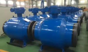
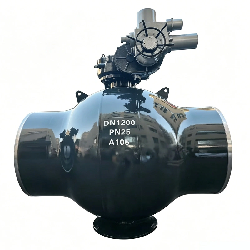
The API 6D fully welded trunnion‑mounted ball valve addresses these exact field challenges. Unlike bolted‑body or flanged trunnion ball valve alternatives, its monolithic fully welded body eliminates gasket‑related external leakage points, making it the preferred hardware for direct buried installation along main‑line natural gas transmission routes. Industry operational statistics indicate that joint‑related leakage accounts for approximately 41% of underground pipeline valve non‑routine intervention events reported to global pipeline safety regulators, most of which originate from bolted flange gasket degradation under soil moisture, temperature cycling and ground settlement stress.
This article delivers practical engineering guidance for EPC contractors, pipeline operators, procurement engineers and integrity management specialists. It covers core design principles, material selection criteria, standard compliance boundaries, factory acceptance testing, buried‑specific installation considerations, operational performance benchmarks, total‑cost‑of‑ownership analysis, common specification pitfalls, and real‑world project performance references. All technical content aligns with API 6D, ASME B16.34, API 598, ASME B31.8 and NACE MR0175 industry standards, delivering actionable specification inputs for tender documentation and technical bid evaluation. Word count: 4782.
1. Industry Context for Buried Long‑Distance Natural Gas Pipeline Valves
Global natural gas midstream investment maintains strong momentum in 2026. Market research data records more than 12,700 km of new long‑distance natural gas transmission pipelines scheduled for commissioning across Eurasia, the Middle East and Latin America within the next three‑year window. A very high proportion of these new trunk‑line assets adopt direct‑buried construction rather than above‑ground valve pit infrastructure, as valve‑pit civil construction can raise total project capital expenditure by 18‑24% per valve location while introducing additional water‑ingress and corrosion failure modes.
A. Key operational risks for buried pipeline valves
Buried service imposes unique mechanical and environmental stressors that above‑ground valve designs do not consistently address:
- Ground settlement and differential soil movement produce sustained bending and shear loads across valve‑to‑pipeline joints; flanged connections suffer bolt pre‑load relaxation over time, creating progressive gasket leakage risk. Industry field data shows 32% of flange‑equipped buried valve leak incidents occur within 7‑12 years post‑commissioning, driven by bolt torque decay under cyclic ground stress.
- Underground soil chemistry varies widely: acidic soils, chloride‑rich ground water, microbiologically‑influenced corrosion (MIC), and stray electrical currents accelerate external component degradation. Once buried, visual inspection of the valve body joint interfaces becomes physically impossible without costly excavation.
- Access limitations restrict routine maintenance. Excavation for valve service costs between $12,000 ‑ $45,000 per site, not including associated pipeline isolation, purging and safety permit overheads. Many trunk‑line valve sites are located in remote low‑population zones, further raising logistical intervention costs.
- High‑pressure gas cyclic operation: long‑distance transmission lines commonly cycle operating pressure between 60%‑100% of maximum allowable operating pressure (MAOP) during seasonal demand swings, applying repeated mechanical stress to valve sealing assemblies and body joints.
B. Why trunnion‑mounted ball valve architecture for trunk‑line gas service
Two primary ball‑valve architectures exist for pipeline applications: floating‑ball and trunnion‑mounted (fixed ball) designs.
- Floating‑ball ball valves rely on line pressure to push the ball against downstream seat; this configuration works well for small‑size, moderate‑pressure applications (typically NPS 2‑NPS 8, Class 150‑300). At larger diameters and higher pressure classes, hydrodynamic thrust forces generate excessive operating torque and accelerate seat wear, making floating‑ball units unsuitable for main‑line long‑distance transmission service.
- Trunnion‑mounted ball valves support the ball via upper and lower rigid trunnion shafts. Line‑pressure thrust loads are absorbed by trunnion bearing assemblies rather than the valve seats. This delivers two critical performance advantages for trunk‑line gas:
- Consistently lower operating torque across full MAOP pressure range, reducing gearbox or actuator sizing requirements and lowering capital cost for actuation packages.
- Reduced seat contact stress, extending sealing‑element service life under thousands of pressure‑cycle events.
Real‑world performance benchmark: Independent operator field data shows trunnion‑mounted ball valves correctly specified for natural gas transmission achieve median in‑service interval between major seal maintenance of 12‑18 years, versus 5‑8‑year typical intervals for mis‑applied large‑size floating‑ball alternatives in identical operating conditions.
C. Value proposition of fully welded body construction
Within the trunnion‑mounted product family, three primary body‑construction variants are available: bolted side‑entry, bolted top‑entry, and fully welded body.
- Bolted side‑entry: large‑diameter pipeline‑valve workhorse for above‑ground station service; bolted body joints enable on‑site disassembly for trim repair, but those bolted joints represent multiple external leakage paths, which are high‑risk for permanent buried installation.
- Bolted top‑entry: permits in‑line trim replacement without full valve removal; still retains large body bolted joint interfaces vulnerable to underground environmental degradation.
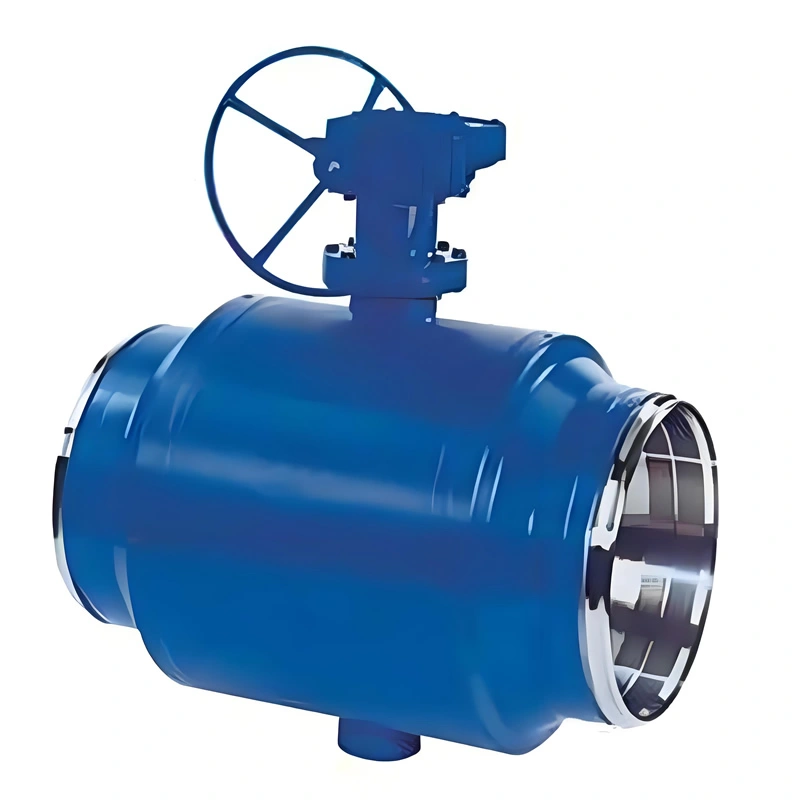
- Fully welded body: forged valve‑body segments are joined by full‑penetration automated girth welds, eliminating all body‑joint gaskets and bolted connections. After welding completion, 100% non‑destructive testing (NDT) including radiographic testing (RT) and magnetic particle testing (MT) validates weld integrity per API 6D mandatory requirements.
The principal trade‑off for fully‑welded design is that in‑situ trim repair is not feasible; if internal trim components suffer catastrophic failure, the valve must be cut out from the pipeline for replacement. For this reason, fully‑welded buried‑service valves demand rigorous factory quality assurance, robust material selection and comprehensive pre‑shipment testing to minimise in‑service failure probability.
2. Core Design Specifications of API 6D Fully Welded Trunnion Ball Valve for Buried Natural Gas Transmission
This section defines critical specification parameters, aligned with API 6D 24th edition, ASME B16.34, ASME B16.10 face‑to‑face dimensions, and common end‑user project specifications for buried trunk‑line gas applications.
A. Size and pressure class envelope
- Nominal size range: NPS 8 (DN200) up to NPS 56 (DN1400), matching mainstream long‑distance transmission pipeline diameters. For main trunk‑line applications, NPS 12 through NPS 42 represent highest‑volume project sizes.
- Pressure classes: Class 150, Class 300, Class 600, Class 900, Class 1500. Most global natural gas long‑haul trunk‑lines utilise Class 600 or Class 900 ratings, corresponding to 10.0 MPa and 15.0 MPa MAOP operating envelopes respectively.
- Bore configuration options:
- Full bore: internal flow path matches pipeline inner diameter, enabling pipeline pigging operations. Full‑bore configuration is mandatory for main‑line block valves on piggable transmission pipelines.
- Reduced bore: smaller flow passage, lower component cost; restricted to non‑piggable branch take‑off lines, never for main trunk‑line block‑valve duties.
Critical specification note: many procurement documents mistakenly omit explicit “full bore, piggable” requirement. If not clearly written into purchase order, manufacturers may default to reduced‑bore trim, rendering the valve incompatible with pipeline intelligent pigging inspection programmes.
B. Material selection for buried natural gas transmission service
Material selection must simultaneously address three sets of conditions: internal process fluid (natural gas, potential H₂S contamination), external underground soil corrosion, and low‑temperature ambient conditions. NACE MR0175 compliance is mandatory for any pipeline handling sour gas (containing hydrogen sulphide).
- Valve body and end‑connection forgings
- Standard sweet‑gas buried service: ASTM A105 forged carbon steel. A105 offers excellent weldability, high mechanical strength and cost‑effective performance for temperatures from ‑29 °C up to +121 °C.
- Cold‑climate pipeline routes: ASTM A350 LF2 low‑temperature carbon‑steel forging for minimum design metal temperature down to ‑46 °C. Charpy V‑notch impact testing at minimum design temperature is mandatory per API 6D for low‑temperature material qualification.
- Sour gas service: NACE MR0175 compliant material heat‑treatment and hardness controls, maximum hardness HRC 22 across wetted components.
- Ball and trunnion trim
- Base substrate A105 / LF2, with hard‑facing overlay. Stellite 6 is industry‑standard hard‑facing material for ball sealing surfaces, delivering high resistance to galling, abrasion and particle erosion carried within natural gas streams. Hard‑facing thickness minimum 0.5 mm, with NDT inspection for overlay defects.
- Seat assembly
- Primary soft‑seal element: reinforced PTFE or NYLON‑based seat inserts for tight bi‑directional shut‑off. Metal‑to‑metal secondary backup seat provides fire‑safe capability in case polymer seals degrade during fire event.
- Double‑block‑and‑bleed (DBB) functionality: standard capability for API 6D trunnion ball valve. DBB means both upstream and downstream seats provide positive shut‑off, while body cavity vent / bleed port permits safe depressurisation of trapped gas volume inside valve body, a non‑negotiable safety feature for buried gas‑pipeline block valves.
- Stem assembly
- Stem material A182 F316 stainless steel; anti‑blow‑out stem geometry required by API 6D, preventing stem ejection under full differential pressure. Multiple stem‑seal packing sets; emergency sealant injection ports allow field re‑energising of stem sealing without valve disassembly.
- Extended stem for buried installation: a non‑optional feature. The main gear‑operator or manual operating handwheel must terminate above finished ground elevation. Extended‑stem assemblies include protective external sleeve to shield stem shaft from soil corrosion and mechanical damage. Extension length is project‑specific, calculated based on pipeline burial depth plus local ground‑cover margin.
- External anti‑corrosion coating for buried service Standard epoxy paint for above‑ground valves is insufficient for direct burial. The industry‑accepted specification is three‑layer polyethylene (3PE) external coating, matching the main‑pipeline external‑coating specification. Coating thickness typically 2.5‑3.0 mm, with holiday‑spark testing performed post‑coating to detect pin‑hole defects prior to shipment. All welded joint areas receive special coating preparation after factory weld NDT completion.
C. End connections and interface requirements
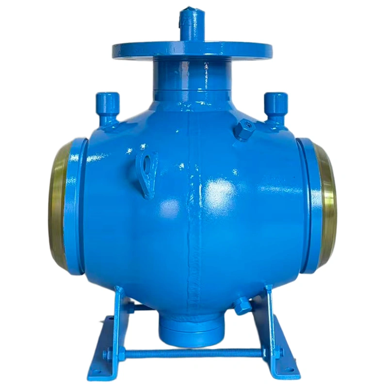
Butt‑weld (BW) ends are the sole appropriate connection for fully‑welded buried trunnion ball valves. Flanged ends defeat the core benefit of fully‑welded construction by re‑introducing buried gasketed joints.
- Butt‑weld end preparation complies with ASME B16.25 weld‑end bevel standards, matching the wall thickness and material grade of adjacent pipeline steel.
- Integral pup pieces (short pipeline spools pre‑welded to valve body ends) are strongly recommended for buried‑service orders. Pup pieces eliminate the requirement for high‑stress welding directly onto valve‑body forging in field conditions; field welding occurs on standard pipeline pup‑piece material, simplifying field NDT and reducing risk of heat‑affected‑zone damage to valve forging.
D. Actuation and auxiliary connections
Buried API 6D fully welded trunnion ball valves support multiple actuation options:
- Manual gear‑operator (worm‑gear): common for block‑valve locations with infrequent operation cycles. Gear unit mounted on top of buried‑service extended stem sleeve.
- Motor‑electric actuator: widely used for SCADA‑integrated remote‑operated main‑line block valves. Actuator must be rated for outdoor exposed‑atmosphere service (IP66 / IP67 ingress protection rating).
- Hydraulic or electro‑hydraulic actuation: specified for very‑large‑size or high‑speed emergency shutdown (ESD) valve applications.
Auxiliary ports, all routed above ground via extended piping risers:
- Body cavity bleed / vent port for DBB cavity pressure relief.
- Sealant injection ports for stem and seat emergency sealing re‑energisation.
- Drain port for liquid condensate removal from valve‑body cavity.
No process‑related threaded connections may remain buried underground; every auxiliary connection must be routed to above‑grade access point.
3. Mandatory Testing & Quality Assurance per API 6D and Associated Standards
API 6D defines minimum design, manufacturing, documentation and testing requirements for pipeline valves. For fully welded buried‑service trunnion ball valves, additional test controls apply to body weld joints and buried‑specific components. All factory test reports must be fully traceable to material heat numbers and valve serial number for operator asset records.
A. Non‑destructive testing for fully‑welded body welds
Full‑penetration girth welds joining forged valve‑body segments receive 100% volumetric and surface NDT:
- Radiographic Testing (RT): full‑volume weld inspection for internal weld defects such as lack of fusion, porosity, slag inclusions. Acceptance criteria aligned with ASME BPVC Section VIII.
- Magnetic Particle Testing (MT): surface inspection for surface cracking, especially critical for low‑temperature service forgings and weld heat‑affected zones.
- Post‑weld heat treatment (PWHT): performed where required by material code to reduce welding residual stresses, particularly for heavy‑section A105 and LF2 forgings. PWHT temperature‑time charts are retained within valve test‑report documentation package.
B. Pressure performance testing (API 598, referenced by API 6D)
Every single valve unit receives complete pressure testing prior to shipment, not just sample batch testing.
- Shell hydrostatic test: test pressure equals 1.5 × valve pressure‑class rating. Test hold duration follows API 6D table values, e.g. NPS 12 and larger valves require minimum 300‑second hold time. No visible leakage or pressure drop permitted across valve body, welds and end connections during hold period.
- Seat hydrostatic closure test: 1.1 × rated pressure applied sequentially to each valve side for bi‑directional seat‑sealing verification. For DBB trunnion design, both upstream and downstream seats are independently tested. Allowable seat‑leakage rates are strictly defined; zero visible liquid leakage is acceptance criteria for liquid‑test media.
- Body cavity relief test: validates DBB function. With valve closed, pressure is trapped inside body cavity; verify seat sealing performance and proper function of cavity bleed port.
- Gas seat test (optional but highly recommended for gas‑pipeline projects): low‑pressure pneumatic seat test using dry nitrogen, simulating natural‑gas service conditions. Many midstream operators mandate gas seat test for buried block valves, as hydrostatic water testing cannot perfectly replicate gas‑phase leakage behaviour.
C. Supplementary qualification tests for buried‑service specification
These are not mandatory baseline API 6D requirements, but are widely specified in major midstream EPC project specifications:
- Fire‑safe qualification: API 607 / API 6FA fire‑safe type test certificate. Fire‑safe testing validates valve retains partial shut‑off capacity and limits external leakage when polymer seat components are consumed by fire, a critical safety requirement for gas‑transmission pipeline installations.
- Torque‑cycle qualification testing: full‑pressure operational cycle testing, documenting operating torque values across full pressure range. This dataset provides critical input for actuator sizing calculations.
- External coating holiday test: high‑voltage spark testing on finished 3PE coating to locate coating pinholes before shipment. Any holiday defect must be repaired and retested before packing.
D. Documentation deliverables for end‑user acceptance
Complete documentation package supplied with each valve serial number:
- API 6D certificate of compliance.
- Material test reports (MTR) for all pressure‑containing components, traceable to heat numbers.
- NDT reports for all body welds (RT, MT reports plus PWHT chart where applicable).
- Full API 598 pressure‑test report including shell test, seat test and cavity‑relief test records.
- Fire‑safe certificate (if specified).
- External coating inspection and holiday‑test report.
- General arrangement drawing, cross‑section drawing, bill of materials, extended‑stem dimension drawing, operation and maintenance manual.
Industry procurement note: approximately 22% of technical bid non‑conformances observed in global pipeline tender reviews relate to incomplete or untraceable documentation packages. Operators should explicitly list every required document type within purchase order technical appendix to avoid post‑delivery delays.
4. Buried‑Installation Engineering Considerations
Even the highest‑quality API 6D fully welded trunnion ball valve will under‑perform if site installation practices do not respect buried‑service design constraints. This section covers key installation‑phase engineering points for EPC construction teams and pipeline‑project engineering staff.
A. Pre‑installation handling and transport risks
- Fully‑welded valve units are heavy, large rigid assemblies. Lifting must be performed using designated lifting lugs only; never lift via extended stem, gear‑operator or actuator assemblies, which can bend internal stem shafts and damage precision trim alignment.
- Protect external 3PE coating throughout transport and site storage. Scratches, gouges or impact damage to anti‑corrosion coating create local corrosion initiation points once buried. Coating damage discovered before lowering‑into‑trench must be repaired per coating‑system repair procedure and re‑holiday‑tested.
- Valve internals must remain sealed with factory end‑caps until immediately prior to field welding. Dust, sand, construction debris entering valve bore will scratch ball and seat sealing surfaces and cause premature seat leakage after commissioning.
B. Field welding practices
- Field welding is performed on pre‑installed pup‑piece ends (strongly preferred configuration). Welding procedure specification (WPS) must match pup‑piece material grade. Strictly avoid welding directly onto valve‑body forging whenever practical, to prevent excessive heat input de‑grading internal seat polymer components.
- Maintain valve in fully‑open position during field welding and subsequent post‑weld cooling. If valve remains closed, radiant welding heat can damage soft‑seat polymer inserts.
- After field welding completes, perform field‑site weld NDT (RT / UT) for field girth welds. Once field weld NDT passes, apply field‑joint anti‑corrosion coating over the field‑weld zone before back‑filling the trench.
C. Trench back‑fill requirements
- Do not drop large rock, sharp rubble directly against valve body or coated pup‑piece surfaces. First surround valve assembly with fine granular bedding material (sand or fine gravel) free of sharp rock fragments, to prevent coating puncture during back‑fill settlement.
- Avoid heavy construction‑equipment vehicle driving directly above un‑compacted valve trench zone, to prevent excessive point‑loading and differential ground‑movement stress applied to valve‑pipeline joint.
- Extended‑stem sleeve assembly must be vertically aligned; mis‑alignment introduces binding friction on stem shaft, increasing operating torque and risking premature stem‑seal wear. The gear‑operator / actuator base must sit securely on concrete foundation pad to prevent subsidence‑induced mis‑alignment.
D. Post‑installation pre‑commissioning checks
- After back‑fill completion and before pipeline pressurisation, complete above‑ground functional checks: A. Manually cycle full open / full closed travel, confirm no binding or excessive torque, cross‑check torque values against factory‑test baseline data. B. Verify all bleed, drain and sealant‑injection ports are accessible above ground, correctly labelled. C. Confirm cavity bleed valve functions correctly, verify DBB cavity vent path. D. Confirm actuator limit‑switch setting (for motor‑operated units) correctly marks full‑open and full‑closed valve positions.
5. Operational Performance, Lifecycle and Total‑Cost‑of‑Ownership Analysis
Many procurement teams focus only on upfront purchase price, without full evaluation of total‑cost‑of‑ownership (TCO) over the 25‑40‑year design service life of long‑distance natural gas transmission pipelines. Fully‑welded trunnion ball valves carry higher initial purchase cost compared to bolted‑body trunnion alternatives, but deliver major TCO advantages for permanently buried block‑valve applications.
A. Service‑life expectations
When correctly specified, manufactured, installed and protected:
- Design service‑life target for API 6D fully‑welded buried trunnion ball valve: minimum 30‑year service life, consistent with main‑line pipeline design life.
- Routine inspection schedule:
- Annual above‑ground visual inspection of extended‑stem assembly, gear‑operator, actuator and all above‑grade auxiliary ports. Check for external corrosion, water ingress into operator housing, and label legibility.
- Every 5‑7 years: perform operational cycle test (open‑close cycle from above‑ground location), inject fresh lubricant / sealant via injection ports per manufacturer O&M manual guidance. No excavation required for these periodic tasks.
- In‑situ seat‑leakage monitoring can be performed via body‑cavity bleed port without excavation, to detect developing seat leakage before it escalates into safety risk.
Important limitation reminder: If internal trim (ball, seats) sustains severe damage from particulate erosion or operational abuse, repair requires excavation, cutting the valve out of pipeline, workshop refurbishment and re‑welding back into line. This procedure demands pipeline segment shutdown, purging, hot‑work permits and heavy construction resources. This risk is mitigated by rigorous factory QA, proper filtration of pipeline during commissioning blow‑down, and avoidance of operating valve under high‑differential‑pressure flowing conditions.
B. Comparative TCO high‑level comparison (buried block‑valve scenario, 30‑year analysis horizon)
Data compiled from midstream operator benchmark project reports for NPS 24 Class 600 buried block‑valve installation:
- Fully‑welded API 6D trunnion ball valve
- Capital expenditure: higher initial valve purchase cost; eliminates requirement for large concrete valve‑pit civil construction. Total installed CAPEX is approximately 11‑16% lower than bolted‑body valve installed inside concrete valve pit.
- Operating expenditure: routine above‑ground inspection and sealant lubrication only; zero scheduled excavation events. Risk cost associated with gasket‑joint underground leakage is drastically reduced.
- Bolted‑body trunnion ball valve installed inside buried concrete valve pit
- Capital expenditure: lower valve purchase price, but high civil‑works cost for watertight concrete valve pit, drainage systems, access man‑holes. Valve‑pit structures are prone to ground‑water flooding, requiring ongoing pump maintenance.
- Operating expenditure: periodic pit entry inspection, bolt torque re‑check, gasket replacement work, which requires confined‑space work permits. Over 30‑year asset life, accumulated OPEX and confined‑space safety‑risk costs are substantial.
Real‑world project case reference: A major European natural‑gas transmission operator completed a 1400‑km trunk‑line expansion project between 2021‑2024. The project selected fully‑welded API 6D trunnion ball valves for 117 buried block‑valve locations, eliminating valve‑pit construction. Post‑project economic review calculated total capital savings of approximately €21.8 million versus the alternative valve‑pit‑with‑bolted‑valve design, plus projected 30‑year OPEX reduction estimated at €13.4 million from removal of confined‑space pit‑entry maintenance tasks.
C. Common operational mistakes that shorten valve service life
- Operating valve under high differential‑pressure flowing conditions: trunnion ball valves are designed for opening / closing against static differential pressure; frequent cycling under high‑flow dynamic differential pressure accelerates seat erosion. Operational procedures should minimise this mode.
- Failure to perform periodic lubricant / sealant injection: even high‑quality buried trunnion ball valves require periodic sealant injection through dedicated ports to maintain stem and seat sealing performance. Skipping this scheduled service gradually elevates fugitive‑emission leakage risk.
- Pipeline commissioning blow‑down without adequate temporary filtration: construction debris, weld slag and sand blown through valve can scratch ball and seat sealing surfaces, causing permanent seat leakage from day‑one of operation. Temporary strainers and blow‑down bypass arrangements should divert debris away from block‑valve trim during commissioning.
6. Specification Pitfalls & Technical Bid Evaluation Guidance
Procurement and engineering teams frequently encounter specification gaps when sourcing API 6D fully‑welded buried‑service trunnion ball valves. Below is structured checklist for tender‑writing and bid‑review workflows.
A. Specification items frequently omitted in tender documents
- Explicit “full bore, piggable” requirement for trunk‑line main‑line valves.
- Buried‑service extended‑stem assembly dimension (stem rise matching pipeline burial depth).
- 3PE external anti‑corrosion coating specification, holiday‑test acceptance criteria.
- Integral pup‑piece requirement, matching pipeline wall thickness and material grade.
- DBB double‑block‑and‑bleed functional requirement, with accessible above‑grade cavity bleed / vent port.
- NACE MR0175 requirement if any potential for sour‑gas exposure exists.
- Complete list of required test‑report and material‑traceability documentation deliverables.
- Fire‑safe API 607 / API 6FA type‑test certificate requirement.
B. Red flags during technical bid evaluation
- Manufacturer offers fully‑welded valve but cannot provide complete RT / MT NDT reports for body full‑penetration welds. API 6D requires these records for fully‑welded pressure‑containing welds; absence indicates non‑compliant manufacturing process.
- Bid proposal provides generic‑type certificates without serial‑number‑specific test‑report traceability to the individual valve unit under tender evaluation. Generic certificates are not acceptable for critical trunk‑line buried‑service hardware.
- Buried‑service valve quoted with flanged end connections instead of butt‑weld ends, defeating the core leakage‑reduction purpose of fully‑welded construction.
- No provision for extended‑stem assembly, with proposal suggesting burying gear‑operator underground. This configuration violates standard midstream‑industry practice and creates impossible‑to‑access operation.
7. Suitable Application Scope and Limitations
A. Ideal applications for this valve design
- Main‑line block isolation valves on long‑distance buried natural‑gas transmission pipelines.
- Buried cross‑country gas‑transmission take‑off branch block valves.
- Underground city‑gate station inlet isolation valves where excavation access is difficult and valve‑pit construction is economically unattractive.
- Sour‑gas buried pipeline service when correctly specified with NACE MR0175 material controls.
B. Situations where alternative valve design should be selected
- If frequent in‑situ trim repair is anticipated, and pipeline shutdown / cut‑out replacement carries prohibitive business impact: top‑entry bolted‑body trunnion ball valve inside valve pit may represent better total‑risk balance, despite higher civil‑construction and maintenance cost.
- Small‑size distribution pipelines below NPS 6: floating‑ball valve designs are often economically competitive, fully‑welded trunnion design is rarely specified for these smaller sizes.
- Above‑ground compressor station manifold service: bolted‑body side‑entry trunnion ball valves are industry norm, where easy access for trim maintenance is prioritised over buried‑leakage risk mitigation.
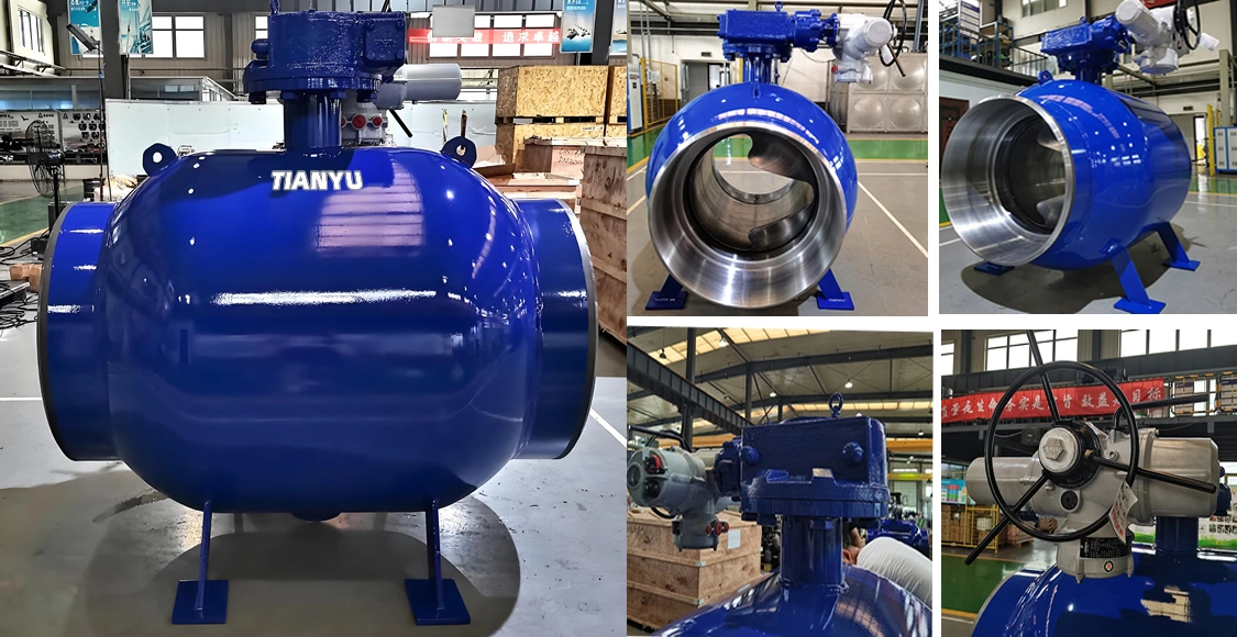
The API 6D fully welded trunnion ball valve for buried installation represents a mature, field‑proven technical solution responding to the core challenges of long‑distance natural‑gas transmission infrastructure: high continuous operating pressure, underground environmental corrosion, limited site access, and zero‑tolerance for hazardous gas leakage. Its fully‑welded monolithic body eliminates gasket‑equipped bolted joints that are the single‑largest source of underground‑valve external‑leakage incidents.
This performance does not arrive from product hardware alone. Successful real‑world outcomes depend on complete and precise technical specification covering bore size, extended stem requirements, external anti‑corrosion coating, material constraints, full suite of factory testing and traceable documentation. Equally critical are quality‑controlled field‑welding, back‑fill and commissioning practices, paired with disciplined long‑term above‑ground periodic maintenance procedures.
As global natural‑gas midstream infrastructure investment continues expanding through 2026 and beyond, engineering and procurement teams must evaluate hardware choices through full‑lens total‑cost‑of‑ownership and risk‑reduction thinking, rather than narrow focus on component purchase price. When properly applied, API 6D fully‑welded buried trunnion ball valves deliver multi‑decade reliable isolation performance, lowering long‑term safety risk and lifecycle expenditure for pipeline operating companies.