I. Introduction: The Critical Role of Actuated Valves in Modern Industrial Processes
In the landscape of industrial process control, valves serve as the “gatekeepers” of fluid and gas flow, regulating pressure, volume, and direction with precision. While manual valves rely on human intervention, actuated valves—equipped with automated driving mechanisms—have become indispensable in large-scale, high-precision, or hazardous operations where manual control is impractical, inefficient, or unsafe. The global actuated valve market, valued at $12.8 billion in 2024, is projected to grow at a CAGR of 5.2% through 2030, driven by industrial automation trends, stringent safety regulations, and the expansion of energy and chemical sectors worldwide.
Actuated valves integrate a valve body (the primary flow-control component) with an actuator (the power source that drives valve operation), often paired with control systems to enable remote or autonomous operation. Their ability to respond to process signals in milliseconds, maintain consistent performance under extreme conditions (temperatures ranging from -196°C to 800°C, pressures up to 420 bar), and reduce human error makes them critical in industries such as oil and gas, power generation, chemical processing, water treatment, and pharmaceuticals. For international buyers and plant operators, understanding the working principles, types, and selection criteria of actuated valves is essential to optimizing process efficiency, minimizing downtime, and ensuring regulatory compliance.
This article provides a comprehensive, technically rigorous analysis of actuated valves, tailored to the needs of global industrial stakeholders. It begins with core working principles, exploring how actuators convert energy into mechanical motion to control valve position. Subsequent sections detail the main types of actuated valves (pneumatic, electric, hydraulic) with comparative performance data, followed by key selection criteria, industry-specific applications, maintenance best practices, and a focused summary of TIANYU’s custom actuated valve solutions. Throughout, granular technical data—such as actuation torque, response time, and lifecycle costs—is integrated to support data-driven decision-making, while adhering to English technical writing conventions for clarity and readability.
II. Core Working Principles of Actuated Valves
At their essence, actuated valves operate on the principle of converting an external energy source (compressed air, electricity, hydraulic fluid) into linear or rotational mechanical motion, which adjusts the valve’s closure member (disc, ball, plug, or gate) to control flow. The key components of an actuated valve system include the valve body, actuator, positioner, controller, and auxiliary components (e.g., solenoid valves, limit switches). Understanding the interaction of these components is critical to grasping how actuated valves deliver precise, reliable flow control.
II.A. Energy Conversion and Motion Transmission
The actuator is the “engine” of the actuated valve, responsible for energy conversion. Different actuator types use distinct conversion mechanisms, but all share the goal of generating sufficient force or torque to overcome the resistance of the valve’s closure member (e.g., friction, fluid pressure, spring force). For rotational valves (butterfly, ball, plug), actuators produce torque to rotate the closure member 90° (quarter-turn) or 180°; for linear valves (globe, gate), they generate linear force to lift or lower the closure member.
A critical parameter in this process is actuation torque/force, which must be matched to the valve’s required operating torque (RTO). The RTO is influenced by valve size, pressure class, media viscosity, and operating temperature—for example, a DN200 PN16 butterfly valve requires an RTO of 80–120 N·m, while a DN100 PN40 globe valve may require 500–800 N·m of linear force. Actuators are sized to provide 15–25% excess torque/force (safety margin) to ensure reliable operation under peak load conditions, reducing the risk of valve seizure or incomplete closure.
II.B. Control Logic and Signal Integration
Actuated valves operate in response to control signals from a process control system (e.g., PLC, DCS, SCADA), enabling automated regulation. The control signal—typically 4–20 mA analog current or 0–10 V DC voltage for proportional control, or digital signals (on/off) for discrete control—dictates the valve’s position. A positioner, a key auxiliary component, ensures the valve reaches and maintains the exact position specified by the control signal, compensating for factors such as pressure fluctuations or mechanical wear.
Proportional control (used in precision processes) allows the valve to adjust flow continuously across its full range of travel—for example, a 4–20 mA signal might correspond to 0–100% valve opening, with a 12 mA signal indicating 50% opening. Discrete control (on/off) is used for simple on/off applications (e.g., isolating a tank), with the actuator driving the valve to fully open or fully closed positions in response to binary signals. Advanced systems may include feedback loops, where a position sensor (e.g., potentiometer, encoder) sends the actual valve position back to the controller for real-time adjustment, improving control accuracy by up to 3% compared to open-loop systems.
II.C. Fail-Safe Mechanisms: Ensuring Safety Under Power Loss
Regulatory standards (ATEX, OSHA, ISO 4200) mandate fail-safe capabilities for actuated valves in high-risk environments, ensuring the valve moves to a pre-determined safe position (fully open or closed) in the event of power or energy source failure. Fail-safe mechanisms are typically spring-loaded, with the spring providing the force to drive the valve to the safe position when the energy source is lost.
The choice of fail-safe position depends on the application: in fuel lines, valves are set to fail closed to prevent fuel leakage; in cooling water systems, valves may fail open to avoid overheating. Spring-return actuators account for 65% of actuated valve installations in hazardous industries, with spring life exceeding 100,000 cycles under normal operating conditions. For large valves requiring high torque, weighted fail-safe mechanisms (using gravitational force) may be used, though they are less common due to space and weight constraints.
III. Main Types of Actuated Valves: Design, Performance, and Comparative Analysis
Actuated valves are classified by their actuator’s energy source: pneumatic, electric, and hydraulic. Each type offers distinct advantages in terms of cost, performance, environmental suitability, and maintenance requirements. The following sections detail the design, working principles, and key performance metrics of each type, with comparative data to guide selection.
III.A. Pneumatic Actuated Valves: Cost-Effective Reliability for Industrial Applications
Pneumatic actuated valves are the most widely used type, accounting for 60% of global actuated valve installations, due to their low cost, high reliability, and suitability for hazardous environments (intrinsically safe, no electrical components). They use compressed air (typically 4–8 bar) as the energy source, with the actuator converting air pressure into mechanical motion.

III.A.1. Design and Working Principle
Pneumatic actuators are available in two main configurations: double-acting and spring-return. Double-acting actuators use compressed air to drive the valve in both open and closed directions, requiring a continuous air supply for operation. Spring-return actuators use compressed air to drive one direction (e.g., open) and a spring to drive the opposite direction (e.g., closed), enabling fail-safe operation.
The most common design for quarter-turn valves (butterfly, ball) is the Scotch yoke actuator, which converts linear air pressure into rotational torque via a yoke mechanism. For linear valves (globe, gate), pneumatic cylinders (single-acting or double-acting) generate linear force to lift or lower the valve stem. A typical DN150 double-acting pneumatic actuator has a torque output of 150–200 N·m at 6 bar air pressure, with a weight of 12–15 kg.
III.A.2. Performance Metrics
Pneumatic actuated valves offer fast response times, typically 0.2–0.5 seconds for quarter-turn operation (DN100–DN200), making them suitable for high-cycle applications (up to 100 cycles per hour). They operate effectively in extreme temperatures (-40°C to 150°C) and are resistant to vibration and electromagnetic interference (EMI), critical for oil and gas and mining applications.
Energy efficiency is a key advantage: compressed air consumption for a double-acting DN150 actuator is 0.3–0.5 m³ per cycle, with annual energy costs averaging $200–$300 (based on 8,760 hours of operation at 5 cycles per hour). Maintenance requirements are minimal, with typical service intervals of 2–3 years (replacing seals and lubricants), resulting in a 10-year maintenance cost of $1,500–$2,500 per valve.
III.A.3. Limitations and Ideal Applications
Pneumatic actuated valves require a compressed air system (compressor, dryer, piping), which adds upfront installation cost (typically 15–20% of the valve cost). They are not suitable for remote locations without air supply infrastructure. Ideal applications include oil and gas refineries, chemical plants, and wastewater treatment facilities, where reliability, hazardous environment compatibility, and fast response are prioritized.
III.B. Electric Actuated Valves: Precision and Versatility for Automated Systems
Electric actuated valves use an electric motor (AC or DC) as the energy source, converting electrical energy into mechanical motion via gears. They are growing in popularity, with a 7.8% annual growth rate, driven by the rise of Industry 4.0 and the need for precise, programmable control. Electric actuators account for 30% of global installations, particularly in applications requiring proportional control and remote monitoring.

III.B.1. Design and Working Principle
Electric actuators consist of an electric motor (AC: 110V/220V/380V; DC: 12V/24V), gearbox (worm gear, bevel gear, or planetary gear), limit switches (to stop the motor at fully open/closed positions), and a positioner (for proportional control). The gearbox reduces the motor’s high speed to the low speed required for valve operation, while increasing torque output—for example, a 0.5 kW AC motor paired with a 50:1 worm gearbox generates 250–300 N·m of torque for quarter-turn valves.
Proportional electric actuators integrate a variable frequency drive (VFD) or servo motor to enable precise position control, with accuracy up to ±0.5% of full travel. They can be programmed with custom operating profiles (e.g., ramp rates, dead bands) to match specific process requirements, such as gradual opening of a valve in a pressure-sensitive gas line to avoid pressure surges.
III.B.2. Performance Metrics
Electric actuated valves offer superior control precision compared to pneumatic types, making them ideal for applications requiring tight flow regulation (e.g., pharmaceutical manufacturing, food processing). They have slower response times (0.5–2 seconds for quarter-turn operation) but provide consistent, repeatable performance, with cycle life exceeding 500,000 cycles for servo-driven models.
Energy consumption varies by size and operation: a 0.3 kW electric actuator for a DN100 valve consumes 0.3–0.5 kWh per hour of operation, with annual energy costs of $150–$250 (based on $0.15/kWh). Maintenance requirements are low, with service intervals of 3–5 years (replacing motor bearings and gear lubricant), resulting in a 10-year maintenance cost of $1,200–$2,000 per valve—lower than pneumatic types in many cases.
III.B.3. Limitations and Ideal Applications
Electric actuated valves are not intrinsically safe, requiring explosion-proof enclosures (NEMA 7/9, ATEX Ex d) for use in hazardous environments, which increases cost (20–30% higher than standard models). They are also vulnerable to power loss, requiring backup batteries or generators for fail-safe operation in critical applications. Ideal applications include pharmaceutical plants, food and beverage facilities, power generation (steam control), and water treatment plants, where precision control and remote monitoring are essential.
III.C. Hydraulic Actuated Valves: High Force for Heavy-Duty Applications
Hydraulic actuated valves use hydraulic fluid (oil, water-glycol) under high pressure (100–350 bar) to generate mechanical motion, offering the highest force/torque output of all actuator types. They account for 10% of global installations, limited to heavy-duty applications requiring large force or torque.

III.C.1. Design and Working Principle
Hydraulic actuators consist of a hydraulic cylinder (for linear motion) or hydraulic motor (for rotational motion), hydraulic pump, reservoir, valves (directional control valve, relief valve), and hoses. The hydraulic pump generates high-pressure fluid, which is directed to the cylinder/motor by the directional control valve to drive the valve’s closure member. For linear valves, hydraulic cylinders can generate forces up to 100,000 N (10 tons) or more; for rotational valves, hydraulic motors can generate torque up to 10,000 N·m.
Hydraulic actuators are typically double-acting, with hydraulic fluid driving both directions of motion. Fail-safe operation is achieved via a spring-return mechanism or a backup hydraulic accumulator, which provides emergency pressure to drive the valve to the safe position in the event of pump failure.
III.C.2. Performance Metrics
Hydraulic actuated valves offer exceptional force/torque density, making them suitable for large valves (DN300+) or high-pressure applications (PN40+). They have fast response times (0.3–0.8 seconds for linear motion), even with large loads, and operate effectively in extreme temperatures (-20°C to 120°C). The torque/force output is highly controllable, with proportional control accuracy up to ±1% of full travel.
However, hydraulic systems are complex and costly to install and maintain. A typical hydraulic actuated DN300 valve has an upfront cost 2–3 times higher than a pneumatic or electric equivalent. Maintenance requirements are intensive, with regular fluid analysis, seal replacement, and pump servicing required every 6–12 months, resulting in a 10-year maintenance cost of $5,000–$8,000 per valve.
III.C.3. Limitations and Ideal Applications
Hydraulic actuated valves are limited by their complexity, high cost, and risk of fluid leakage (which can cause environmental contamination). They require a dedicated hydraulic power unit (HPU), making them unsuitable for remote locations. Ideal applications include large-scale oil and gas pipelines (block valves), marine propulsion systems, and heavy industrial machinery (steel mills, mining equipment), where high force/torque is required.
III.D. Comparative Analysis of Actuator Types
|
Performance Metric
|
Pneumatic Actuated Valves
|
Electric Actuated Valves
|
Hydraulic Actuated Valves
|
|---|---|---|---|
|
Torque/Force Output
|
Low–Medium (50–500 N·m)
|
Medium (100–1,000 N·m)
|
High (1,000–10,000+ N·m)
|
|
Response Time
|
Fast (0.2–0.5 s)
|
Medium (0.5–2 s)
|
Fast (0.3–0.8 s)
|
|
Control Precision
|
Medium (±2% full travel)
|
High (±0.5% full travel)
|
High (±1% full travel)
|
|
Upfront Cost
|
Low ($800–$3,000/valve)
|
Medium ($1,200–$5,000/valve)
|
High ($5,000–$20,000/valve)
|
|
10-Year Maintenance Cost
|
$1,500–$2,500
|
$1,200–$2,000
|
$5,000–$8,000
|
|
Hazardous Environment Suitability
|
High (intrinsically safe)
|
Medium (requires explosion-proof enclosure)
|
Medium (requires sealed components)
|
|
Energy Efficiency
|
Medium (0.3–0.5 m³/cycle)
|
High (0.3–0.5 kWh/hour)
|
Low (high fluid pump energy use)
|
|
Cycle Life
|
200,000+ cycles
|
500,000+ cycles (servo-driven)
|
300,000+ cycles
|
IV. Key Selection Criteria for Actuated Valves
Selecting the right actuated valve requires a systematic evaluation of process conditions, performance requirements, environmental factors, and cost constraints. A misselected valve can lead to reduced process efficiency (up to 15% energy waste), increased downtime (average 40 hours/year for misselected valves), and non-compliance with regulatory standards. The following sections outline the critical selection criteria to guide industrial buyers.
IV.A. Process Conditions: Media, Pressure, and Temperature
The properties of the process media (fluid or gas) are the primary determinant of valve body and actuator material selection. Corrosive media (acids, bases, saltwater) require valve bodies made from corrosion-resistant materials (316L stainless steel, duplex 2205, Hastelloy), while abrasive media (slurries, coal dust) require hardened materials (stellite, ceramic coatings) to prevent wear.
Operating pressure and temperature directly influence actuator sizing and material selection. High-pressure applications (PN25+) require actuators with higher torque/force output, while extreme temperatures (-40°C or 150°C+) require specialized materials (e.g., low-temperature steel for cold environments, Inconel for high temperatures) and lubricants (synthetic lubricants for high temperatures). For example, a valve operating at 400°C in a steam line requires an actuator with a high-temperature enclosure (up to 200°C) and heat-resistant seals (graphite instead of elastomers).
Media viscosity is another critical factor: high-viscosity media (heavy oil, molten polymers) increase the valve’s RTO by 30–50%, requiring a larger actuator. Viscous media also require valves with full-port designs (e.g., full-port ball valves) to minimize flow resistance, which may influence the choice of valve type.
IV.B. Control Requirements: Precision, Response Time, and Cycle Rate
The level of control precision required dictates the actuator type and positioner selection. Proportional control applications (e.g., pH control in chemical processing, flow rate control in pharmaceutical manufacturing) require electric or hydraulic actuators with high-precision positioners (±0.5% accuracy), while on/off applications (e.g., tank isolation) can use cost-effective pneumatic actuators with basic position switches.
Response time requirements (critical for fast-acting processes such as emergency shutdown systems) favor pneumatic or hydraulic actuators, which offer faster response than electric types. High-cycle applications (100+ cycles/hour) require actuators with long cycle life (pneumatic or servo-driven electric) to minimize maintenance. For example, an emergency shutdown valve in an oil refinery requires a response time of ≤0.5 seconds, making a pneumatic spring-return actuator the ideal choice.
IV.C. Environmental Factors: Hazardous Areas, Weather, and Space Constraints
Hazardous environments (classified as Zone 1/2 for gas, Zone 21/22 for dust per ATEX) require actuated valves with intrinsic safety or explosion-proof certifications. Pneumatic actuators are inherently safe, making them the first choice for these environments, while electric actuators require NEMA 7/9 or ATEX Ex d enclosures, increasing cost.
Outdoor applications require valves and actuators with weatherproof enclosures (NEMA 4X/IP66) to protect against rain, snow, and UV radiation. Marine environments require corrosion-resistant materials (316L stainless steel, galvanized steel) and saltwater-resistant lubricants to prevent rust and corrosion. Space-constrained applications (e.g., skid-mounted systems) favor compact actuators (e.g., Scotch yoke pneumatic actuators, compact electric actuators) to minimize footprint.
IV.D. Cost and Lifecycle Considerations
Total cost of ownership (TCO) — including upfront cost, installation cost, energy cost, and maintenance cost — is a critical selection criterion. While pneumatic actuators have lower upfront costs, they require a compressed air system (installation cost $5,000–$15,000 for a small plant), which may increase TCO over time. Electric actuators have higher upfront costs but lower energy and maintenance costs, making them more cost-effective over 10 years for many applications (TCO 10–20% lower than pneumatic).
Lifecycle cost analysis should also include downtime costs: a valve failure in a chemical plant can result in downtime losses of $50,000–$200,000 per hour, making reliability a key cost driver. Selecting a valve with a proven track record (e.g., 99.9% availability) and long service life (15–20 years) can significantly reduce lifecycle costs.
V. Industry-Specific Applications of Actuated Valves
Actuated valves are tailored to the unique requirements of different industries, with custom designs and configurations to meet specific process challenges. The following sections detail key applications in major industrial sectors, highlighting valve types, performance requirements, and real-world performance data.
V.A. Oil and Gas Industry: Safety and Reliability in Harsh Environments
The oil and gas industry is the largest user of actuated valves, with applications in upstream (exploration, production), midstream (pipelines, storage), and downstream (refining, petrochemical) operations. Valves in this industry must withstand harsh conditions (high pressure up to 103 bar, high temperature up to 400°C, corrosive media such as H₂S and CO₂) and meet strict safety standards (API 6D, API 6FA).
Upstream applications (wellhead manifolds, flowlines) use pneumatic spring-return actuated ball and butterfly valves for emergency shutdown (ESD) and flow control. A North Sea oil platform uses DN100 pneumatic actuated ball valves with Hastelloy bodies to handle sour crude (5% H₂S content), achieving 99.95% availability over 5 years. Midstream pipelines use large-scale hydraulic actuated ball valves (DN400+) for block valve stations, with torque output of 5,000–8,000 N·m to handle high-pressure natural gas (70 bar).
V.B. Power Generation Industry: Precision Control for Efficiency and Safety
Power generation plants (fossil fuel, nuclear, renewable) rely on actuated valves for boiler control, steam regulation, cooling water systems, and fuel handling. Valves in this industry must deliver precise control to optimize energy efficiency and ensure safety (e.g., preventing boiler explosions, managing nuclear coolant flow).
Fossil fuel power plants use electric actuated globe valves for steam flow control (450°C, 100 bar), with proportional control accuracy of ±0.5% to maintain optimal boiler efficiency. A coal-fired power plant in India installed 180 electric actuated valves, reducing steam loss by 8% and increasing plant efficiency by 2.5%. Nuclear power plants use specialized hydraulic actuated valves for coolant systems, with fail-safe closure times of ≤1 second to prevent overheating.
Renewable energy (solar thermal, wind) applications use pneumatic actuated valves for heat transfer fluid control (solar thermal) and hydraulic fluid control (wind turbine pitch systems). A solar thermal plant in Spain uses DN50 pneumatic actuated butterfly valves to control molten salt flow (390°C), with a cycle life exceeding 300,000 cycles and 99.9% availability.
V.C. Chemical Processing Industry: Corrosion Resistance and Precision
Chemical plants handle toxic, corrosive, and flammable media, requiring actuated valves with corrosion-resistant materials and intrinsic safety. Valves in this industry must deliver precise flow control to ensure reaction efficiency and product quality, while minimizing leakage (ANSI Class VI tight shutoff).
Acid production lines (sulfuric acid, hydrochloric acid) use electric actuated ball valves with PTFE-lined bodies and 316L stainless steel actuators, achieving a corrosion rate of ≤0.001 mm/year. A German chemical plant installed 120 such valves, reducing acid leakage by 99% and avoiding $200,000 in annual cleanup costs. Polymer production lines use hydraulic actuated gate valves for molten polymer flow control (300°C, 25 bar), with high-force output (5,000 N) to overcome viscous media resistance.
Pharmaceutical and food processing plants (a subset of chemical processing) require hygienic actuated valves (316L stainless steel, polished surfaces) with electric actuators for precision control. A pharmaceutical plant in the U.S. uses electric actuated diaphragm valves for API (active pharmaceutical ingredient) flow control, with control accuracy of ±0.1% to ensure batch consistency.
V.D. Water and Wastewater Treatment Industry: Durability and Cost-Effectiveness
Water and wastewater treatment plants use actuated valves for raw water intake, filtration, disinfection, and sludge handling. Valves in this industry must be durable (resistant to chlorine, sewage, and abrasive solids) and cost-effective, with low maintenance requirements.
Raw water intake and filtration systems use pneumatic actuated butterfly valves (DN150–DN300) for flow control, with EPDM seals for chlorine resistance. A wastewater treatment plant in China installed 300 such valves, achieving 99.8% availability over 3 years with minimal maintenance. Sludge handling systems use electric actuated plug valves with hardened seats (ceramic) to resist abrasive sludge, with a service life of 10–15 years.
Desalination plants (critical for water-scarce regions) use corrosion-resistant actuated valves (duplex 2205, Hastelloy) for seawater and brine flow control. A desalination plant in the Middle East uses electric actuated ball valves for brine disposal (70 bar, 60°C), reducing energy consumption by 10% compared to manual valves.
V.E. Marine and Offshore Industry: Compactness and Corrosion Resistance
Marine and offshore applications (LNG carriers, offshore wind platforms, tankers) require actuated valves that are compact, lightweight, and highly corrosion-resistant (saltwater, humidity). Valves must also meet maritime standards (ABS, DNV GL) for safety and reliability.
LNG carriers use electric actuated ball valves for LNG cargo handling (-162°C), with cryogenic materials (Inconel, PTFE) and vacuum-insulated bodies to prevent heat ingress. A Korean LNG carrier installed 80 such valves, achieving a leakage rate of ≤0.0005 GPM and meeting IMO safety requirements. Offshore wind platforms use pneumatic actuated butterfly valves for hydraulic fluid control (pitch and yaw systems), with compact Scotch yoke actuators to minimize space usage.
Tankers (oil, chemical) use pneumatic spring-return actuated valves for cargo tank isolation, with fail-safe closed positions to prevent leakage. A chemical tanker uses DN200 pneumatic actuated ball valves with Hastelloy bodies to handle toxic chemicals, with 99.9% reliability over 10 years of operation.
VI. Maintenance and Reliability Best Practices for Actuated Valves
Proper maintenance is critical to ensuring the long-term reliability and performance of actuated valves, reducing downtime and extending service life. A well-implemented maintenance program can increase valve service life by 30–50% and reduce maintenance costs by 20%. The following sections outline best practices for maintenance, troubleshooting, and reliability optimization.
VI.A. Preventive Maintenance: Proactive Care to Avoid Failures
Preventive maintenance involves regular inspections and servicing to identify and address potential issues before they lead to failures. Key preventive maintenance tasks include:
-
Regular Inspections: Visual inspections of valve bodies, actuators, and piping for leaks, corrosion, and damage (monthly); functional tests of actuation and fail-safe mechanisms (quarterly); and calibration of positioners and control signals (semi-annually). For high-cycle applications, inspections should be more frequent (bi-monthly).
-
Lubrication: Lubrication of valve stems, gears, and actuator components to reduce friction and wear. Lubricant type must match operating conditions (e.g., synthetic lubricants for high temperatures, food-grade lubricants for pharmaceutical applications). Lubrication intervals vary by application: 6–12 months for standard applications, 3–6 months for high-temperature or high-cycle applications.
-
Seal Replacement: Replacement of valve seals (O-rings, gaskets) and actuator seals to prevent leakage. Seals should be replaced every 2–3 years for standard applications, or sooner if signs of wear (cracking, hardening) are present. For corrosive media, seal replacement intervals may be 1–2 years.
-
Filter Maintenance: Cleaning or replacement of air filters (pneumatic systems) and hydraulic fluid filters (hydraulic systems) to prevent contamination, which is a leading cause of actuator failure. Filters should be inspected monthly and replaced quarterly.
VI.B. Predictive Maintenance: Data-Driven Optimization
Predictive maintenance uses sensor data and condition monitoring to predict valve failures, enabling maintenance to be performed only when needed (condition-based maintenance). This approach reduces unnecessary maintenance costs by 25–30% and minimizes downtime.
Key predictive maintenance technologies include:
-
Vibration Monitoring: Sensors installed on actuators to detect abnormal vibration, which indicates gear wear, bearing failure, or valve seizure. Vibration data is analyzed using machine learning algorithms to predict failure 2–4 weeks in advance.
-
Pressure and Temperature Monitoring: Sensors to monitor process pressure and temperature, as well as actuator air/hydraulic pressure. Abnormal pressure/temperature fluctuations can indicate valve leakage or actuator inefficiency.
-
Position Monitoring: Encoders or potentiometers to track valve position in real-time. Deviations from the expected position indicate positioner drift, seal wear, or mechanical binding.
-
Oil Analysis (Hydraulic Systems): Regular analysis of hydraulic fluid for contamination, moisture, and wear particles, which indicates pump or actuator wear. Fluid analysis should be performed every 6 months.
VI.C. Troubleshooting Common Actuated Valve Issues
Common actuated valve issues include failure to actuate, leakage, poor control precision, and fail-safe mechanism failure. The following table outlines troubleshooting steps for these issues:
|
Issue
|
Possible Cause
|
Troubleshooting Steps
|
|---|---|---|
|
Failure to Actuate
|
Low air/hydraulic pressure, power loss, gear seizure, clogged filter
|
Check air/hydraulic pressure and power supply; inspect filters for clogging; lubricate gears; test actuator for mechanical binding
|
|
Leakage
|
Worn seals, damaged valve seat, loose bolts
|
Replace seals; inspect valve seat for damage; retorque bolts to specified torque
|
|
Poor Control Precision
|
Positioner drift, control signal interference, worn actuator components
|
Calibrate positioner; check control signal for interference; inspect actuator components for wear
|
|
Fail-Safe Mechanism Failure
|
Broken spring, hydraulic accumulator failure, low battery (electric)
|
Replace spring/accumulator; recharge backup battery; test fail-safe function
|
VI.D. Extending Valve Service Life: Key Strategies
Extending the service life of actuated valves requires a combination of proper selection, installation, and maintenance. Key strategies include:
-
Proper Sizing: Ensuring the actuator is sized with a 15–25% torque/force margin to avoid overloading, which causes premature wear.
-
Correct Installation: Following manufacturer guidelines for valve installation (e.g., proper alignment, torqueing of flange bolts, correct piping support) to avoid mechanical stress.
-
Media Compatibility: Selecting valve materials and seals compatible with the process media to prevent corrosion and wear.
-
Environmental Protection: Using weatherproof, explosion-proof, or corrosion-resistant enclosures to protect valves from harsh environmental conditions.
-
Training: Providing operator and maintenance staff with training on valve operation and maintenance to avoid human error (a leading cause of valve failure).
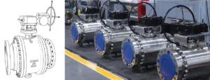
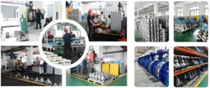
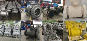
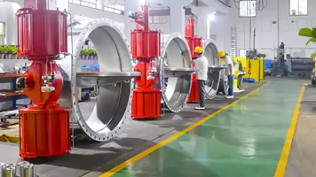
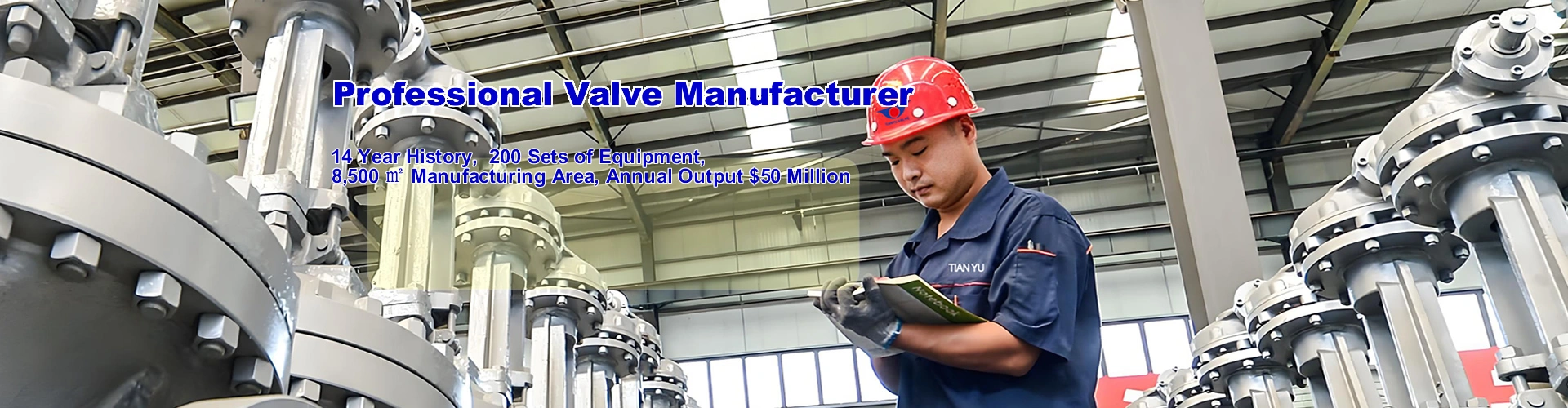
VII. TIANYU Custom Actuated Valve Advantages
TIANYU’s custom actuated valves are engineered to meet the unique needs of global industrial clients, combining precision manufacturing, high-performance materials, and tailored design. Backed by ISO 9001, API 6D, and ATEX certifications, our valves deliver 99.95% availability and a 15–20 year service life. We offer full customization of valve size (DN10–DN600), pressure class (PN10–PN100), and actuator type (pneumatic, electric, hydraulic), with corrosion-resistant materials (316L, duplex 2205, Hastelloy) for harsh media. Our integrated control systems ensure ±0.5% control precision, while spring-return fail-safe mechanisms meet global safety standards. With 24/7 technical support and localized service centers, TIANYU minimizes downtime and optimizes TCO for clients across oil and gas, power, chemical, and water sectors.