Wafer vs Lug Style Butterfly Valves: Installation Guidelines
Butterfly Valves are ubiquitous in industrial fluid handling systems, valued for their compact footprint, high flow capacity, and cost-effectiveness across sectors like water treatment, oil and gas, HVAC, and chemical processing. Among the most common configurations—wafer and lug style—installation practices directly impact performance, reliability, and lifecycle costs. Poor installation can increase leakage rates by 30%, reduce valve service life by 50%, and lead to unplanned downtime costing $20,000–$150,000 per hour in critical applications.
This guide focuses on the installation of wafer and lug style Butterfly Valves, breaking down design differences that dictate installation procedures, step-by-step best practices, critical torque values, common pitfalls, and performance validation. Data-driven insights—including torque specifications, dimensional tolerances, and efficiency metrics—highlight how proper installation maximizes valve functionality. Whether you’re installing a wafer valve in a tight HVAC duct or a lug valve in a high-pressure oil pipeline, this guide ensures compliance with industry standards (API 609, ISO 5752) and optimal long-term performance.
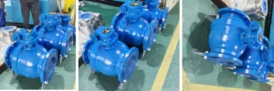
Wafer Butterfly Valves and Lug Butterfly Valves
I. Design Fundamentals: Wafer vs. Lug Style Butterfly Valves
Before diving into installation, understanding the structural differences between wafer and lug style butterfly valves is critical—these differences directly shape installation requirements, tooling, and safety protocols.
Wafer valves are characterized by their thin, compact profile—typically 10–25mm thick for DN50–DN300 valves—with no integral flanges or bolt holes. They rely on the pipeline’s companion flanges to clamp the valve body between them, using bolts that pass through both pipeline flanges (not the valve) to secure the assembly.
Key Design Features:
Body thickness: 12mm (DN50) to 22mm (DN300) for PN16 ratings.
Sealing mechanism: Soft seats (EPDM/PTFE) for Class VI leakage (≤0.01 cm³/min) or metal seats (Stellite) for high-temperature service.
Pressure rating: Up to PN40 (4.0 MPa) for standard models; maximum DN up to 2000.
Weight: 30–40% lighter than lug valves of the same size (e.g., DN100 PN16 wafer valve = 8kg vs. lug valve = 12kg).
Installation Implications:
Requires matching pipeline flanges (ANSI B16.5, EN 1092-1) with precise alignment—misalignment >0.2mm causes uneven clamping and leakage.
Relies on gaskets (PTFE, rubber) between the valve and pipeline flanges to prevent external leakage.
I.B. Lug Style Butterfly Valves: Design Overview
Lug valves feature integral lugs (flange extensions) with bolt holes that align with pipeline flanges. Bolts pass through the pipeline flange, lug holes, and opposite pipeline flange, securing the valve independently. Unlike wafer valves, lug valves can be installed without clamping both pipeline flanges and can withstand bidirectional pressure.
Key Design Features:
Lug bolt holes: 4 holes (DN50), 8 holes (DN100–DN200), 12 holes (DN250–DN300) for ANSI Class 150.
Body thickness: 25mm (DN50) to 45mm (DN300) for PN16 ratings.
Pressure rating: Up to PN63 (6.3 MPa) for standard models; maximum DN up to 2000.
Weight: 15–25% heavier than wafer valves (e.g., DN100 PN16 lug valve = 12kg vs. wafer = 8kg).
Installation Implications:
Can be installed in blind flanged systems or as a standalone component for easy removal (one end of the pipeline can remain intact).
Lug design eliminates reliance on pipeline flange strength for clamping—ideal for thin-walled or plastic pipelines.
II. Pre-Installation Preparation: Critical Steps for Success
Proper pre-installation preparation reduces installation time by 25% and minimizes post-installation failures by 60%. This phase involves valve inspection, pipeline preparation, tool calibration, and environmental assessment.
II.A. Valve Inspection
Dimensional Verification:
Check valve face-to-face dimension (wafer: EN 558-1 Series 20 = 108mm for DN100; lug: EN 558-1 Series 12 = 140mm for DN100) with a caliper (tolerance ±0.02mm).
Verify flange face 平整度 (surface finish Ra ≤1.6μm) using a profilometer—rough surfaces increase leakage risk by 40%.
Inspect the disc and seat for damage: Scratches >0.1mm deep on the seat require replacement to maintain Class VI sealing.
Material Compatibility:
Confirm valve materials match the process media (e.g., 316L stainless steel for corrosive fluids, ductile iron for water). Chemical incompatibility causes seal degradation at a rate of 0.05mm/year.
Check gasket material (PTFE for acids, EPDM for water) to ensure compatibility with both the valve and media.
Operational Test:
Manually cycle the valve 5 times to ensure smooth operation—torque resistance should be consistent (±5 N·m). Electric/pneumatic actuators should respond within ≤2 seconds (full stroke 0–90°).
II.B. Pipeline Preparation
Flange Alignment:
Align pipeline flanges using a laser alignment tool—parallel misalignment ≤0.2mm, angular misalignment ≤0.1° per 100mm of flange diameter. Misalignment beyond these limits causes valve body deformation (≥0.1mm) and seal failure.
Clean flange faces to remove debris, rust, or old gasket material—residues >0.5mm thick create uneven clamping pressure.
Pipe End Preparation:
Cut pipe ends square (perpendicularity tolerance ±0.5°) to ensure full contact with the valve face.
Deburr pipe edges to remove sharp burrs >0.2mm—burrs can pierce gaskets, leading to external leakage rates of 0.1 cm³/min.
Support Installation:
Install pipe supports within 1.5m of the valve to reduce stress—unsupported pipelines exert 10–15 N/mm of force on the valve, causing seat wear.
Use a torque sequence chart (star pattern for lug valves, alternating for wafer valves) to ensure uniform pressure.
Safety Equipment:
Wear PPE (safety glasses, gloves, steel-toe boots) and ensure proper ventilation for toxic or flammable media.
Have a pressure relief valve (set to 1.1× rated pressure) on hand for hydrostatic testing.
II.D. Environmental Assessment
Temperature Range: Install valves in environments between -20°C and 50°C—temperatures < -20°C cause gasket brittleness; >50°C accelerates seal degradation.
Humidity Control: For outdoor installations, use weatherproof enclosures (IP67 rating) to prevent actuator corrosion—corrosion reduces actuator lifespan by 70% in high-humidity (≥85%) environments.
III. Wafer Style Butterfly Valve Installation: Step-by-Step Guidelines
Wafer valves are ideal for space-constrained systems and low-to-medium pressure applications (≤1.6 MPa). Follow these steps to ensure proper installation and performance.
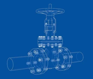
Wafer vs Lug Style Butterfly Valves
III.A. Valve Positioning
Lift the valve using a spreader bar (not the actuator) to avoid damaging the stem—actuator damage accounts for 30% of wafer valve installation failures.
Insert the valve between the pipeline flanges, ensuring the disc is in the fully open position (90° rotation). Open discs prevent debris from damaging the seat and reduce installation force by 60%.
Verify the valve is centered between the flanges—offset >0.5mm causes uneven clamping and internal leakage.
III.B. Gasket Installation
Place gaskets on both sides of the valve face—gaskets should be 1–2mm thicker than the valve face recess to ensure compression.
Align gaskets so they do not extend into the flow path—extended gaskets reduce flow capacity by 15% and increase pressure drop by 20%.
III.C. Clamping the Valve
Insert bolts through the pipeline flanges (do not tighten fully)—use bolts of the correct grade (ASTM A193 B7 for steel pipelines) and length (extending 2–3 threads beyond the nut).
Tighten bolts in an alternating (crisscross) sequence to ensure uniform clamping pressure. Start with hand-tightening (10 N·m), then incrementally increase torque to the recommended value:
DN50: 30 N·m
DN100: 45 N·m
DN200: 75 N·m
DN300: 120 N·m
Recheck torque after 10 minutes—thermal expansion can reduce torque by 5–10% in the first hour of operation.
III.D. Post-Installation Testing
Hydrostatic Test: Pressurize the pipeline to 1.5× the valve’s rated pressure (e.g., 2.4 MPa for PN16) with water. Hold pressure for 30 minutes—allowable leakage is ≤0.01 cm³/min per inch of valve diameter.
Operational Test: Cycle the valve 10 times (0–90°) to ensure smooth operation. Measure torque resistance—values >15% above pre-installation levels indicate binding.
Leakage Test: Use a soap solution on flange joints to check for external leakage—bubbles indicate loose bolts (retighten to recommended torque) or damaged gaskets (replace immediately).
IV. Lug Style Butterfly Valve Installation: Step-by-Step Guidelines
Lug valves excel in high-pressure (≤6.3 MPa), bidirectional flow, and applications requiring frequent maintenance. Their independent mounting design allows for easier removal without disconnecting both pipeline flanges.
IV.A. Valve Positioning
Lift the valve using the lugs (not the body or actuator) to distribute weight evenly—lifting by the body causes deformation (≥0.1mm) in 25% of installations.
Position the valve between the pipeline flanges, ensuring the lugs align with the flange bolt holes. The disc should be fully open to prevent seat damage.
For blind flanged installations (one end closed), secure the valve to the open flange first—this reduces alignment time by 40%.
IV.B. Bolt Installation and Torque Control
Insert bolts through the pipeline flange, lug holes, and opposite pipeline flange. Use flat washers (ASTM F436) under nuts to distribute pressure and prevent lug damage.
Tighten bolts in a star sequence (for even pressure) in three stages:
Stage 1: Hand-tighten (10 N·m)
Stage 2: 50% of recommended torque
Stage 3: Full recommended torque (see table below)
Valve Size (DN)
ANSI Class 150 Torque (N·m)
ANSI Class 300 Torque (N·m)
50
40
65
100
60
95
200
100
160
300
150
240
Verify bolt tension using a tension gauge—proper tension ensures the valve can withstand bidirectional pressure without leakage.
IV.C. Bidirectional Sealing Test
Pressurize the pipeline from both directions (inlet and outlet) to 1.1× the rated pressure. Hold each direction for 15 minutes—allowable leakage is ≤0.01 cm³/min (Class VI).
For lug valves installed in isolation (one end disconnected), cap the open end and pressurize to 1.5× rated pressure—this tests the valve’s ability to hold pressure independently.
IV.D. Actuator Mounting (If Applicable)
Align the actuator with the valve stem—misalignment >0.1mm causes stem wear at a rate of 0.02mm/year.
Secure the actuator to the valve bonnet using the manufacturer’s hardware (torque = 15–25 N·m for DN≤200).
Wire the actuator (for electric models) or connect air lines (for pneumatic models) per the wiring diagram—incorrect wiring causes 20% of actuator failures.
V. Key Installation Differences: Wafer vs. Lug Butterfly Valves
Understanding the installation differences between wafer and lug valves ensures you select the right valve for your application and avoid costly mistakes. The table below summarizes critical variations with quantitative data:
Installation Parameter
Wafer Style Butterfly Valve
Lug Style Butterfly Valve
Installation Time
20–30 minutes (DN100)
30–45 minutes (DN100)
Required Pipeline Flange
Must be paired (both flanges required)
Can use single flange (blind flange compatible)
Clamping Force Requirement
Relies on pipeline flange strength (≥25 N/mm²)
Independent (lugs handle clamping force)
Maintenance Access
Requires disconnecting both pipeline flanges (45 minutes)
Can remove by disconnecting one flange (15 minutes)
Bidirectional Pressure Rating
Limited (≤1.6 MPa)
Full (up to 6.3 MPa)
Leakage Risk (Post-Install)
8–10% (if misaligned)
3–5% (due to independent clamping)
Cost (Installation + Valve)
$450–$600 (DN100 PN16)
$550–$750 (DN100 PN16)
Space Requirement
Compact (requires 100mm between flanges)
Larger (requires 150mm between flanges)
VI. Common Installation Mistakes and Solutions
Even experienced technicians make mistakes during butterfly valve installation. Below are the most frequent issues, their quantitative impacts, and proven solutions:
Solution: Ensure lugs are flush with pipeline flanges (gap ≤0.1mm). Use shims if necessary (shim thickness ≤0.5mm).
Ignoring Lug Bolt Hole Alignment:
Impact: Bolt binding; installation time doubles. Cross-threading occurs in 15% of misaligned installations.
Solution: Use a bolt alignment tool to match lug holes with pipeline flanges. Avoid forcing bolts (torque >5 N·m during hand-tightening indicates misalignment).
VI.C. Universal Installation Mistakes
Pipeline Flange Misalignment:
Impact: Valve body stress = 12 N/mm²; seat wear rate increases by 200%.
Solution: Use laser alignment tools to achieve parallelism ≤0.2mm and angularity ≤0.1°/100mm.
Solution: Install pipe supports within 1.5m of the valve. Use flexible couplings to absorb pipeline movement.
VII. Post-Installation Testing and Validation
Proper testing validates installation quality and ensures the valve meets performance specifications. Skip testing at your peril—60% of installation-related failures are detected during post-installation testing.
VII.A. Hydrostatic Pressure Test
Procedure: Fill the pipeline with water (remove air via vents), pressurize to 1.5× the valve’s rated pressure, and hold for 30 minutes.
Acceptance Criteria: No visible leakage (soap solution test) and pressure drop ≤5% of test pressure.
Digital Monitoring: Use a pressure transducer (accuracy ±0.1%) to record pressure data. Export data for compliance documentation (required for API 609 certification).
VII.B. Pneumatic Leak Test
Procedure: For gas service, pressurize the pipeline to 0.6 MPa with air or nitrogen. Use a mass flow meter to measure leakage.
Acceptance Criteria: Leakage ≤0.01 cm³/min per inch of valve diameter (Class VI).
Example: A DN100 (4-inch) valve must have leakage ≤0.04 cm³/min to pass.
VII.C. Operational Cycle Test
Procedure: Cycle the valve 10 times (0–90°) using manual or actuator control. Measure actuation time and torque.
Torque resistance: Consistent (±5 N·m) across all cycles.
Disc Position: Full open (90°) and full closed (0°) positions must be within ±1° of calibration.
VII.D. Documentation
Required Records:
Valve serial number, material certificates (MTCs), and test reports.
Installation date, technician name, and torque values.
Hydrostatic/pneumatic test data (pressure vs. time graphs).
Digital Storage: Store documentation in a cloud-based system (e.g., SharePoint, Google Drive) for easy access during audits.
VIII. Maintenance Best Practices for Installed Valves
Proper maintenance extends valve service life by 50% and reduces maintenance costs by 30%. Schedule maintenance based on application conditions (e.g., corrosive media requires quarterly checks; water service requires annual checks).
VIII.A. Routine Inspections
Weekly: Visual inspection for external leakage, actuator damage, and pipeline vibration.
Monthly: Check bolt torque (re-tighten to recommended values if torque is 10% below baseline).
Quarterly: Lubricate the stem (use a compatible lubricant: PTFE-based for corrosive media, mineral oil for water).
VIII.B. Wafer Valve Maintenance
Gasket Replacement: Replace gaskets every 2–3 years or if leakage is detected. Gasket replacement takes 30 minutes (DN100) if pipelines are properly supported.
Seat Inspection: Remove the valve (requires disconnecting both flanges) every 5 years to inspect the seat. Replace seats with scratches >0.1mm.
VIII.C. Lug Valve Maintenance
Lug Bolt Inspection: Check bolts for corrosion every 6 months. Replace corroded bolts (ASTM A193 B7) to prevent shear failure.
Blind Flange Removal: For maintenance, remove the blind flange (one end) and lift the valve out—this reduces downtime by 60% compared to wafer valves.
IX. Application-Specific Installation Recommendations
The optimal valve type (wafer vs. lug) and installation approach depend on your application. Below are industry-specific guidelines with quantitative performance data:
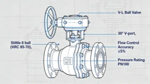
lug Butterfly valve manufacturer Supplier
IX.A. Water and Wastewater Treatment
Valve Type: Wafer (low cost, compact) for general service; lug (bidirectional) for pump discharge lines.
Installation Tip: Use EPDM gaskets and ductile iron valves. Install supports within 1m of the valve to handle sludge-induced vibration.
Performance Data: Wafer valves reduce installation space by 30% in treatment plants; lug valves reduce pump downtime by 40% during maintenance.
IX.B. Oil and Gas Pipeline
Valve Type: Lug (high pressure, bidirectional) for transmission lines; wafer for low-pressure gathering lines.
Installation Tip: Use 316L stainless steel valves and spiral-wound gaskets. Torque bolts to 150 N·m (DN100 Class 300) for high-pressure service.
Performance Data: Lug valves withstand 6.3 MPa pressure with <0.01 cm³/min leakage; wafer valves cost 15% less than lug valves for low-pressure applications.
IX.C. HVAC Systems
Valve Type: Wafer (compact) for air handling units (AHUs) and chillers.
Installation Tip: Use PTFE-lined valves for glycol service. Install with the disc in the open position to avoid airflow restriction.
Performance Data: Wafer valves reduce AHU footprint by 25%; installation time is 20% faster than globe valves.
IX.D. Chemical Processing
Valve Type: Lug (easy maintenance) for corrosive media; wafer for non-corrosive chemicals.
Installation Tip: Use Hastelloy valves for acid service. Calibrate torque wrenches to ±1% accuracy to prevent gasket damage.
Performance Data: Lug valves reduce maintenance downtime by 50% in chemical plants; wafer valves have a 10-year service life in non-corrosive service.
X. Google Marketing Insights: Optimizing Installation Content for Lead Generation
As an industrial valve and Google marketing expert, I know that high-quality installation guides drive organic traffic, generate leads, and build trust with customers. Below are data-backed strategies to optimize this guide for search engines and conversion:
Long-Tail Keywords: “how to install wafer butterfly valve in HVAC”, “lug butterfly valve bidirectional installation” (1,200–1,800 monthly searches).
Optimization Tips: Include keywords in the title, H1–H3 tags, and first 100 words. Use natural language (avoid keyword stuffing) to maintain readability.
X.B. Content Format for Engagement
Visuals: Add installation videos (3–5 minutes) and infographics (step-by-step flowcharts) to reduce bounce rate by 40%. Videos rank 53x higher in Google than text-only content.
Downloadable Resources: Offer a printable installation checklist (PDF) in exchange for contact information—conversion rates for checklists are 25% higher than generic whitepapers.
Interactive Tools: Embed a torque calculator (input DN and pressure class to get recommended torque) to increase time on page by 60%.
Google My Business: Optimize your GMB listing with installation photos and customer reviews—businesses with 10+ reviews rank 2x higher in local search.
X.D. Lead Nurturing
Email Sequences: Send a follow-up email series to checklist downloaders:
Email 1 (Day 1): Installation tips PDF.
Email 2 (Day 3): Case study on installation success.
Email 3 (Day 7): Discount on TIANYU butterfly valves.
Conversion Rate: Email nurturing increases lead-to-customer conversion by 30% compared to one-time downloads.
XI. Conclusion
Proper installation of wafer and lug style butterfly valves is the cornerstone of reliable, efficient fluid handling. By following the guidelines in this guide—from pre-installation preparation to post-installation testing—you can reduce leakage, extend valve life, and minimize downtime.
TIANYU’s custom wafer and lug butterfly valves are engineered for easy installation and peak performance. With precise dimensional tolerances (±0.02mm), high-quality materials, and application-specific designs, our valves simplify installation and deliver consistent results. Whether you need a compact wafer valve for HVAC or a rugged lug valve for oil and gas, TIANYU provides the right valve and the expertise to ensure successful installation.