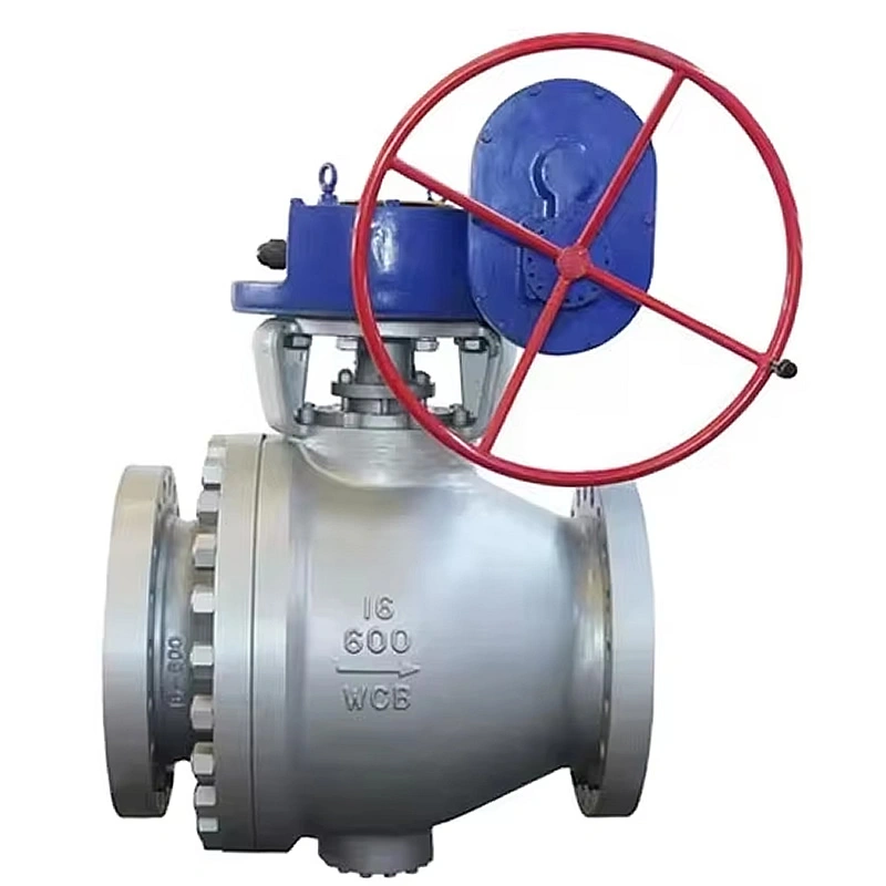
The trunnion-mounted configuration is a key structural advantage that sets this valve apart from floating ball designs. The ball is supported by upper and lower trunnions, which are precision-fitted with self-lubricating bearings, ensuring the ball rotates only along a predefined axis without lateral movement. This design absorbs the thrust generated by media pressure, transferring it to the valve body rather than the valve seat. As a result, shaft wear and bearing pressure are minimized, even under maximum rated pressure conditions, leading to reduced operating torque and extended seat life.
The trunnions are manufactured using precision grinding technology, achieving a surface roughness of Ra 0.8μm and ensuring coaxiality with the ball within 0.01mm. The self-lubricating bearings—made from a composite material of PTFE and bronze—eliminate the need for additional lubrication, reducing maintenance requirements and avoiding contamination of the process media. A drainage hole in the lower trunnion allows for the removal of condensed water and debris from the valve cavity, preventing internal corrosion and ensuring smooth operation.
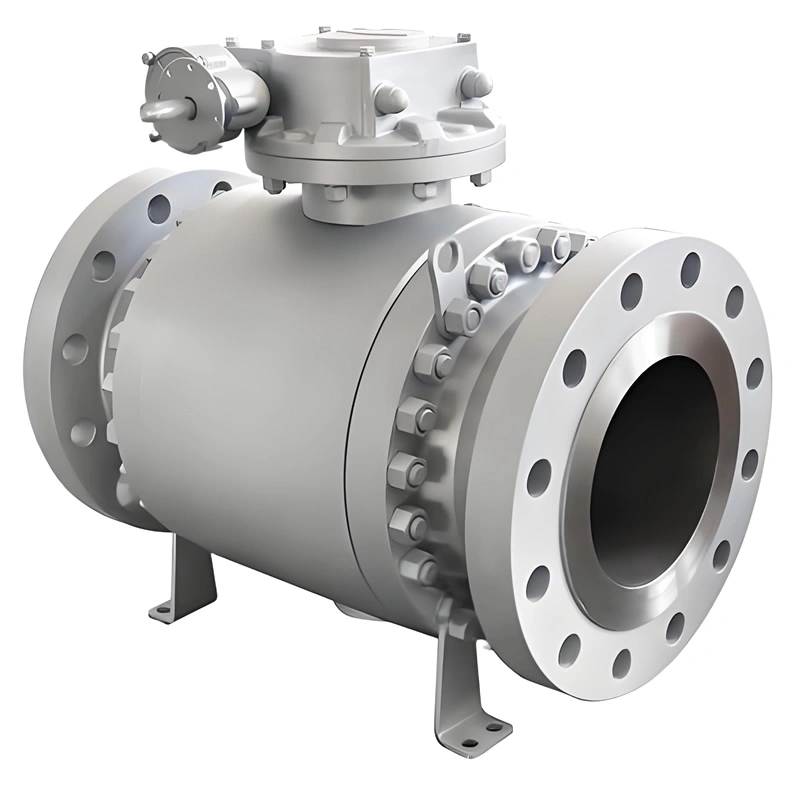
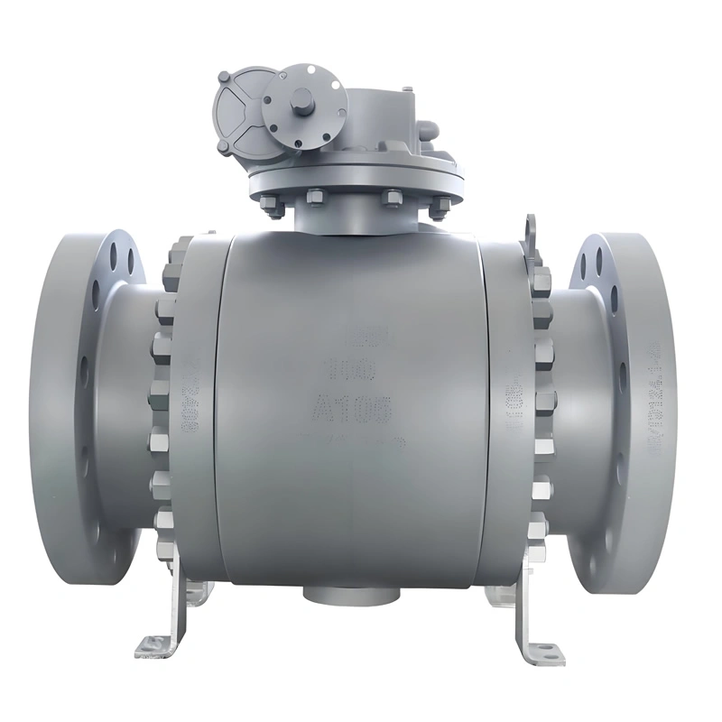
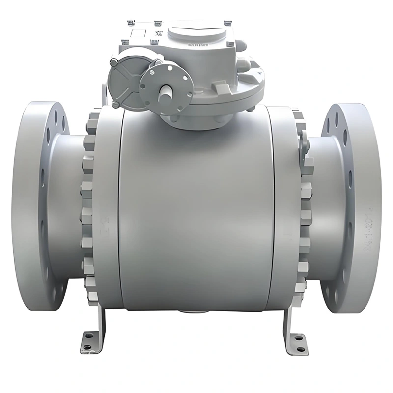
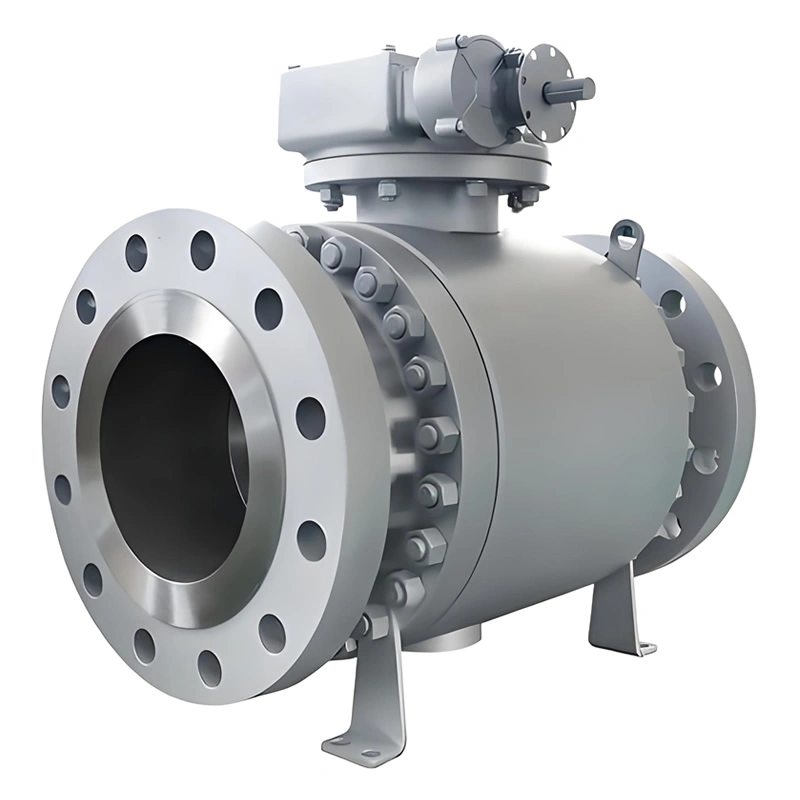
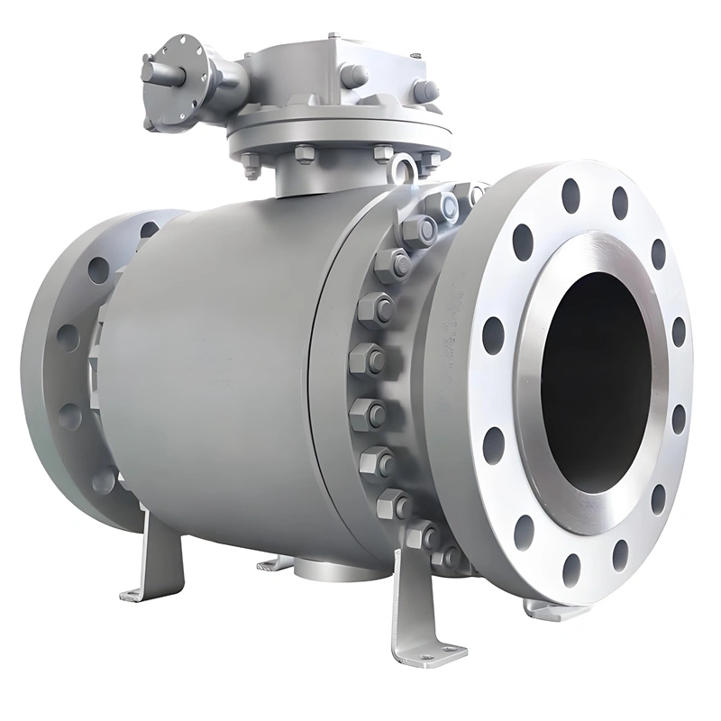
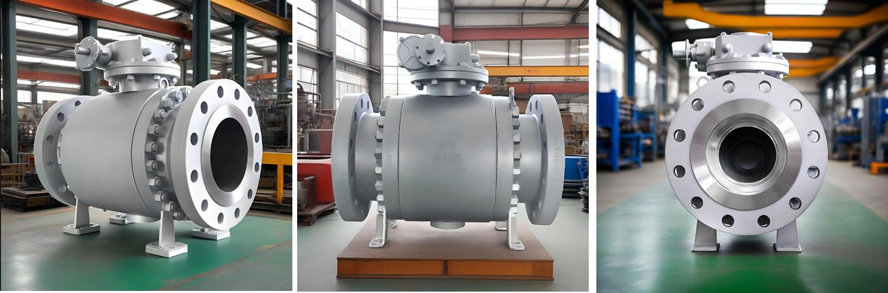
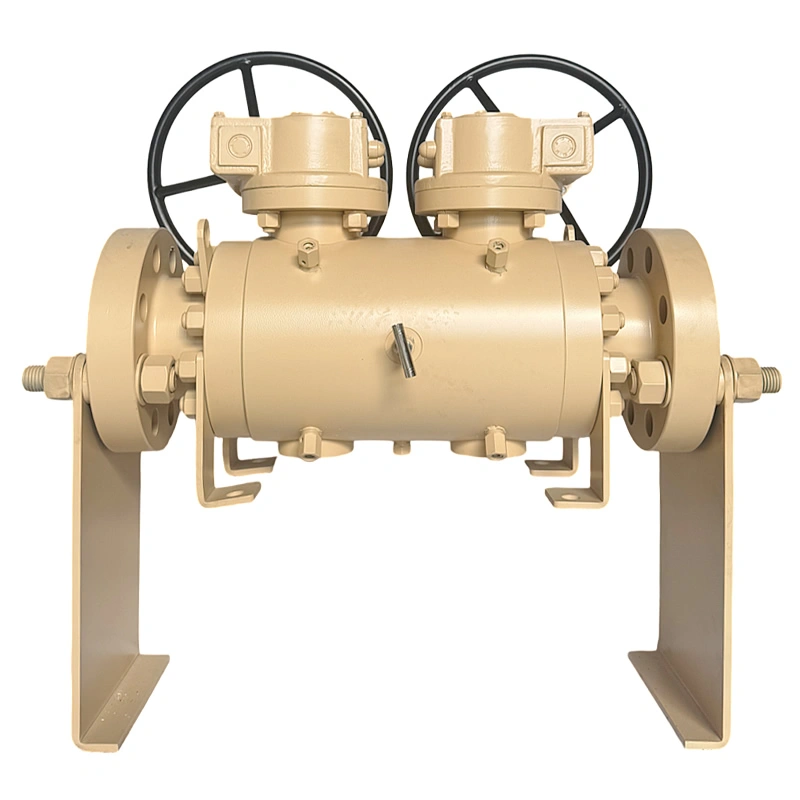
The valve body is divided into three sections—left end, middle body, and right end—connected by high-strength bolts and nuts. This three-piece design offers significant advantages in terms of maintenance and versatility. When internal components (such as the ball, seat, or packing) require inspection, repair, or replacement, the connecting bolts can be removed, and the middle body can be separated from the end flanges without disconnecting the valve from the pipeline. This reduces maintenance time and downtime, critical for continuous production processes.
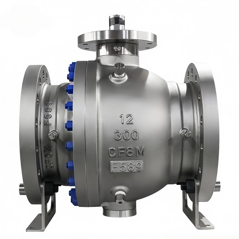
The sealing between the three body sections utilizes a metal gasket combined with an O-ring, creating a double-sealing effect that prevents leakage even under high pressure and temperature fluctuations. The middle body—housing the ball, seat, and trunnion assembly—features a honed inner cavity with a surface finish of Ra 1.6μm, minimizing fluid flow resistance and enhancing flow efficiency. The bolted connection also allows for easy adjustment of the body alignment, ensuring proper seating of the ball and optimal sealing performance.
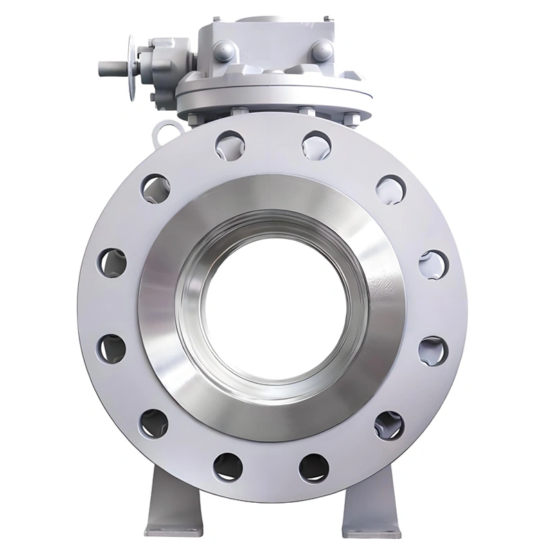
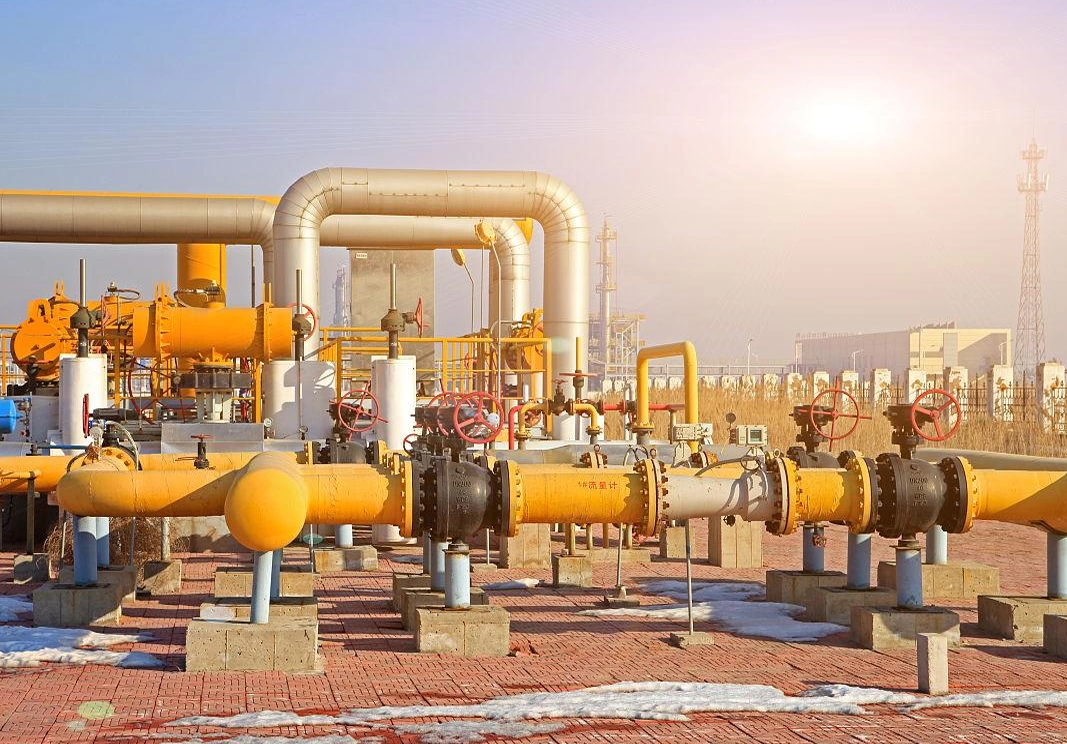
Unlike reduced-port valves, which restrict flow and increase pressure drop, this valve features a full-port design where the bore diameter is equal to the nominal diameter of the pipeline. This design minimizes pressure loss, reducing energy consumption and optimizing the efficiency of fluid transfer systems. For applications involving viscous media, slurries, or particulate-laden fluids, the full-port design prevents clogging and ensures consistent flow rates.
The full-port ball is precision-machined to ensure a smooth flow path, with no sharp edges or obstructions that could cause turbulence. The Stellite overlay on the ball surface not only enhances wear resistance but also maintains the integrity of the flow path even after prolonged use. In oil & gas pipeline applications, the reduced pressure drop translates to significant cost savings by reducing the required pump horsepower.
Safety is a top priority in the design of TIANYU’s trunnion mounted ball valve, which incorporates multiple safety mechanisms to mitigate risks in industrial environments:
- Fire-Safe Design: As per API 607/6FA standards, the valve is equipped with a metal-to-metal backup sealing system. In the event of a fire that damages the polymer seat inserts, the metal seat base and ball come into contact, forming a tight seal that prevents media leakage. The valve body and bonnet are also designed to withstand high temperatures without deformation, ensuring structural integrity during a fire.
- Anti-Static Protection: The anti-static device—consisting of a spring-loaded contact pin—establishes a continuous electrical connection between the ball, stem, and body. This diverts static electricity, which can accumulate during the opening and closing of the valve, to the ground, eliminating the risk of static sparks that could ignite flammable vapors or gases.
- Anti-Blowout Stem: The stem is designed with a enlarged shoulder at the bottom, which engages with the valve bonnet. Under excessive media pressure, the shoulder is pressed against the bonnet, preventing the stem from being blown out of the valve body—a critical safety feature that prevents catastrophic leakage.
- Over-Torque Protection: For automated actuators, an over-torque protection device is integrated to prevent damage to the valve or actuator. If the operating torque exceeds the rated limit (e.g., due to valve jamming or debris accumulation), the device automatically cuts off the power supply (for electric actuators) or releases air pressure (for pneumatic actuators), protecting the valve components from mechanical failure.
The valve’s sealing system is engineered to deliver reliable performance across a wide range of operating conditions. The dual-material seat design combines the strength of the A105 steel base with the flexibility of PTFE or graphite inserts, ensuring a tight seal even in the presence of minor surface irregularities on the ball. The seats are preloaded with stainless steel springs, which provide a constant sealing force against the ball.
A key advantage of this design is its self-compensating capability. As the seat insert wears over time due to repeated contact with the ball, the spring automatically pushes the seat forward, compensating for the wear and maintaining the sealing force. This self-compensating feature extends the service life of the seats and reduces the frequency of maintenance. Additionally, the bidirectional sealing capability of the seats allows the valve to be installed in either flow direction, simplifying pipeline design and installation.
TIANYU maintains strict control over raw material procurement to ensure the quality of its valves. Forged steel A105 and other key materials are sourced from certified suppliers with ISO 9001 certification, and each batch of material is accompanied by a Material Test Certificate (MTC) detailing chemical composition, mechanical properties, and heat treatment history.
Upon arrival at the factory, raw materials undergo rigorous inspection:
- Chemical Composition Analysis: Using a direct-reading spectrometer, the chemical composition of the forging blanks is verified to ensure compliance with ASTM standards. Any deviation from the specified composition results in the rejection of the batch.
- Mechanical Property Testing: Tensile, yield, and impact tests are conducted on sample specimens from each batch using a universal testing machine. The impact test is performed at -20℃ to ensure the material maintains toughness in low-temperature environments.
- Non-Destructive Testing (NDT): Ultrasonic Flaw Detection (UT) is used to inspect the internal structure of the forging blanks, detecting defects such as cracks, inclusions, and porosity. Magnetic Particle Inspection (MPI) is performed on the surface of the blanks to identify surface cracks or discontinuities. Only materials passing all NDT inspections are approved for further processing.
The forging of valve body, bonnet, and ball components is performed using a 10,000-ton hydraulic press, ensuring the material is fully densified and free of internal defects. The forging process follows a strict sequence:
- Blanking: Raw steel bars are cut to the required length using a high-precision bandsaw, ensuring uniform blank size.
- Heating: The blanks are heated in a natural gas-fired controlled atmosphere furnace to 1200–1250℃, a temperature range that maximizes material plasticity while avoiding grain growth.
- Forging: The heated blanks are forged into the approximate shape of the valve components using multiple passes. The forging ratio is maintained at ≥3:1, ensuring the internal grain structure is refined and uniform, enhancing mechanical properties.
- Cooling: After forging, the components are cooled in a slow cooling pit to below 500℃, preventing thermal stress and cracks caused by rapid cooling.
The ball is manufactured using a one-piece forging process, eliminating the structural weaknesses associated with welded balls. After forging, the ball blanks undergo shot blasting treatment to remove surface oxide scale and improve surface roughness, preparing them for subsequent machining.
Heat treatment is a critical step in enhancing the mechanical properties of the valve components. The forging components (body, bonnet, ball) undergo normalizing heat treatment:
- Normalizing: The components are heated to 890–920℃ in a controlled atmosphere furnace, held at this temperature for 1–2 hours (depending on thickness), and then cooled in air. This process refines the grain structure, eliminates internal stress, and ensures uniform mechanical properties. After normalizing, the hardness of the A105 components is controlled between 140–180 HB, balancing strength and machinability.
The 17-4PH stainless steel valve stems undergo a two-step heat treatment process:
- Solution Treatment: Heated to 1040℃ for 1 hour, then water-cooled to dissolve precipitates and achieve a uniform austenitic structure.
- Aging Treatment: Heated to 480℃ for 4 hours, then air-cooled to form a martensitic structure with precipitates, enhancing strength and hardness.
The Stellite overlay welding on the ball surface is followed by post-weld heat treatment at 600℃ to eliminate welding stress and ensure a strong bond between the overlay layer and the A105 base material.
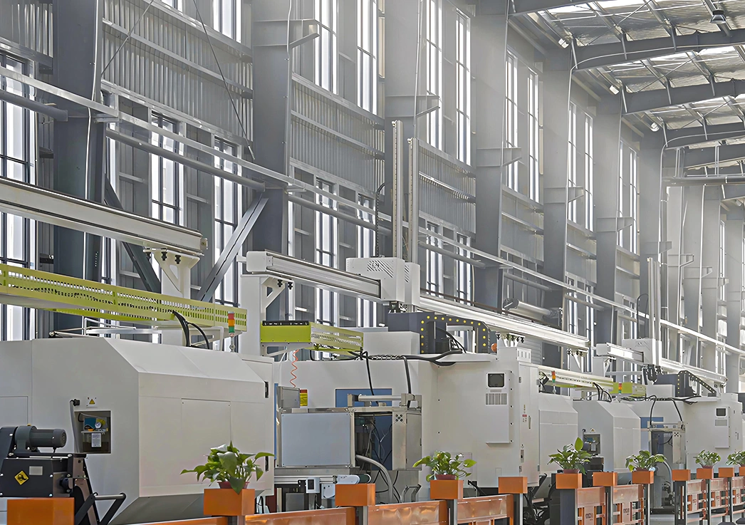
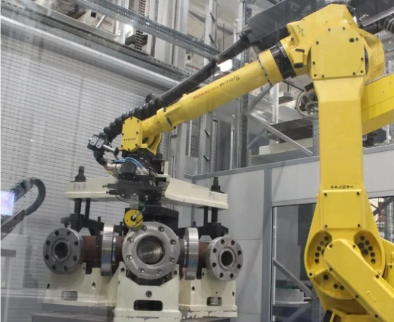
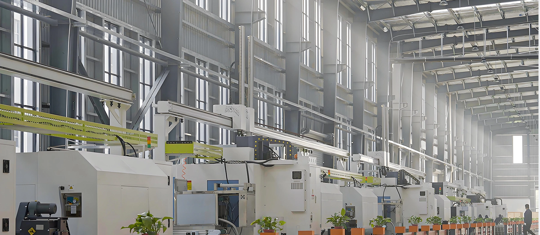
Mechanical processing of valve components is performed using high-precision CNC (Computer Numerical Control) equipment, including CNC lathes, CNC milling machines, and CNC grinding machines, ensuring dimensional accuracy and consistency.
Key machining steps include:
- Valve Body Machining: The flange end faces, inner cavity, and bolt holes are machined on CNC vertical lathes. The flange end face flatness error is controlled within ≤0.02mm/m, and the sealing surface roughness is Ra 1.6μm, ensuring a tight fit with the gasket. The inner cavity is honed to achieve a smooth surface finish, reducing flow resistance.
- Ball Machining: The ball undergoes multiple machining operations, including turning, grinding, and lapping. The outer surface of the ball is ground to a roundness error of ≤0.005mm, and the sealing surface is lapped to a roughness of Ra 0.025μm, ensuring precise contact with the valve seat.
- Stem Machining: The stem is turned and ground to achieve a smooth surface (Ra ≤0.4μm) and precise dimensional tolerance (±0.01mm), ensuring smooth operation and effective sealing with the packing.
All machining operations are performed in a controlled environment to minimize the impact of temperature and humidity on dimensional accuracy. Each component is inspected using coordinate measuring machines (CMM) to verify compliance with design specifications.
The assembly process follows strict procedures to ensure the valve components are correctly installed and aligned:
- Component Cleaning: All machined components are thoroughly cleaned to remove oil, debris, and metal particles, preventing contamination of the sealing surfaces.
- Seat and Ball Installation: The valve seats are installed in the middle body, and the springs are preloaded to ensure the correct sealing force. The ball is carefully positioned between the seats, and the trunnions are fitted with bearings.
- Stem and Packing Installation: The stem is inserted into the bonnet, and the packing is installed in layers, with each layer compressed to the specified torque to ensure effective sealing.
- Body Assembly: The three body sections are aligned and bolted together, with the bolts tightened in a crisscross pattern to ensure uniform clamping force.
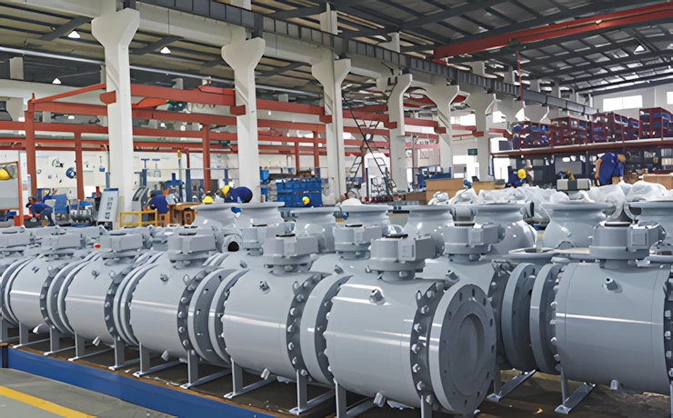
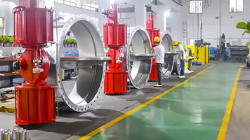
After assembly, each valve undergoes a comprehensive testing program in accordance with API 6D and ISO 5208 standards:
- Pressure Testing: Hydrostatic shell test (1.5 times the rated pressure) and seat test (1.1 times the rated pressure) are performed to check for leakage. The valve is held at the test pressure for a specified duration (≥30 minutes), and no leakage is permitted.
- Operational Testing: The valve is cycled open and closed multiple times to verify smooth operation, correct actuator performance, and proper alignment of the ball and seats.
- Fire-Safe Testing: Sample valves are subjected to fire testing in accordance with API 6FA standards, verifying the integrity of the metal-to-metal sealing system after exposure to high temperatures.
- Anti-Static Testing: The resistance of the anti-static device is measured to ensure it is ≤10Ω, confirming effective static discharge.
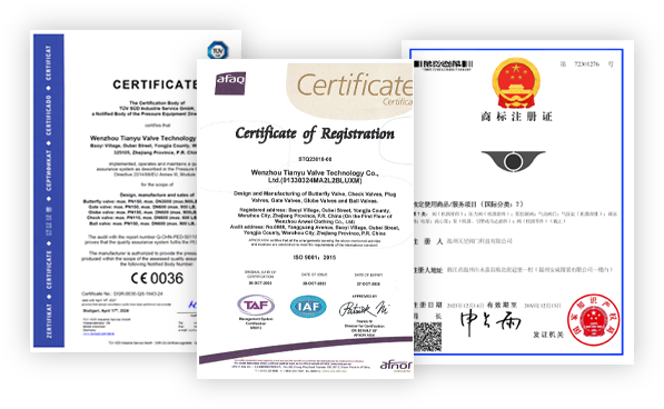
TIANYU operates a comprehensive quality management system certified to ISO 9001:2015, covering all stages of the product lifecycle—from design and development to manufacturing, testing, and after-sales service. A dedicated quality control team monitors each process, conducting regular audits and inspections to ensure compliance with standards and customer requirements.
Each valve is assigned a unique serial number, enabling full traceability from raw material procurement to delivery. Quality records—including material test certificates, machining reports, and test results—are retained for a minimum of 10 years, providing customers with complete transparency and confidence in the product.