III. Feature Description
A. Side-Entry Structure: Maintenance Efficiency & Structural Stability
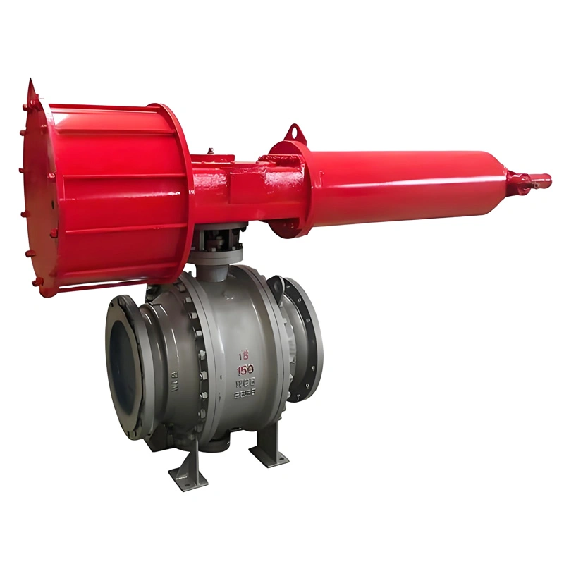
The side-entry design is a defining feature that sets this valve apart from top-entry alternatives. Unlike top-entry models, which require complete removal from the pipeline for internal maintenance, the TIANYU side-entry ball valve allows technicians to access the ball, stem, and sealing components by simply removing the side cover bolts. This design reduces maintenance downtime by up to 60% in critical applications such as oil refinery process lines, where unplanned shutdowns can result in significant production losses.
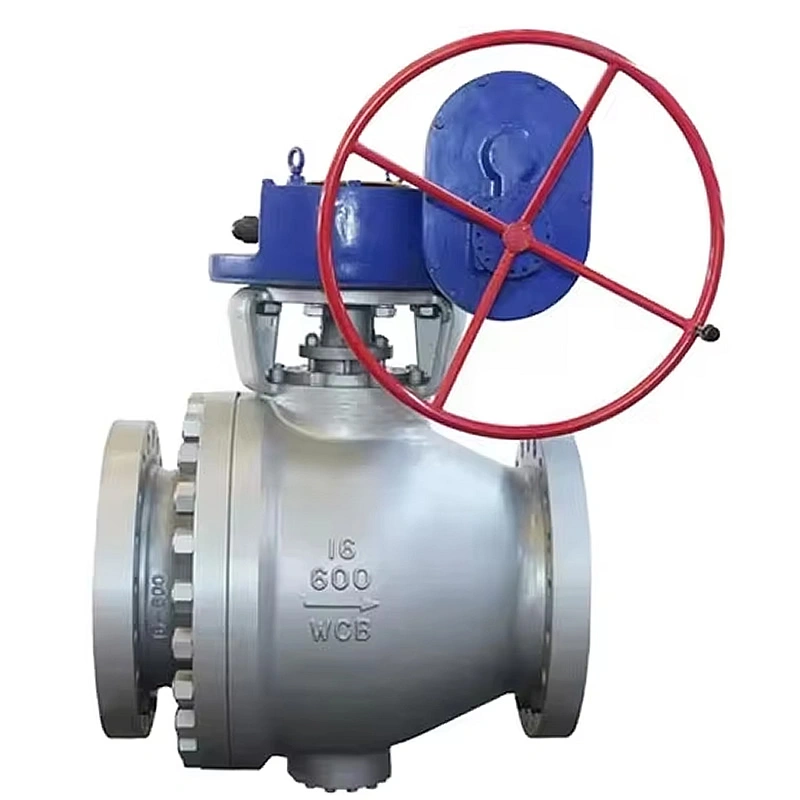
Additionally, the side-entry configuration provides superior structural stability for large-diameter valves (such as DN250). The stem is supported at both ends, minimizing deflection during operation and reducing wear on the sealing surfaces. This dual support structure also enhances the valve’s ability to withstand high-pressure fluctuations, a common challenge in natural gas transmission pipelines.
B. API 607 Fire-Safe Design: Critical Safety Assurance
Fire safety is a non-negotiable requirement in oil, gas, and chemical industries, and the TIANYU valve’s fire-safe system is engineered to meet the rigorous demands of API 607 7th Edition. The valve undergoes a 30-minute fire test, where it is exposed to temperatures exceeding 750℃, simulating an industrial fire scenario. During the test, the reinforced PTFE primary seal melts, but the graphite packing and secondary metal-to-metal seal expand to fill the gap, preventing the escape of flammable media.
This design not only complies with global safety standards but also minimizes the risk of secondary explosions and environmental contamination. In offshore oil platforms or onshore refineries, where fire hazards are prevalent, this feature provides operators with critical time to shut down systems and mitigate risks.
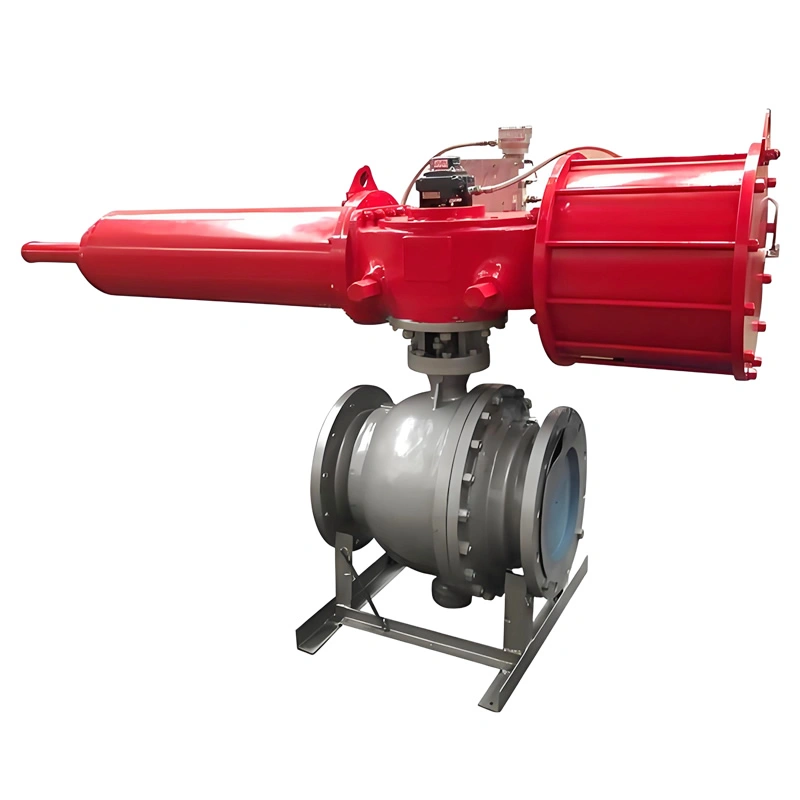
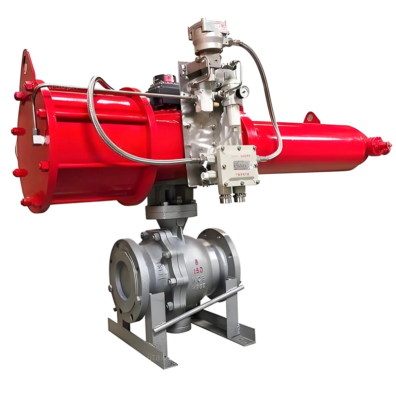
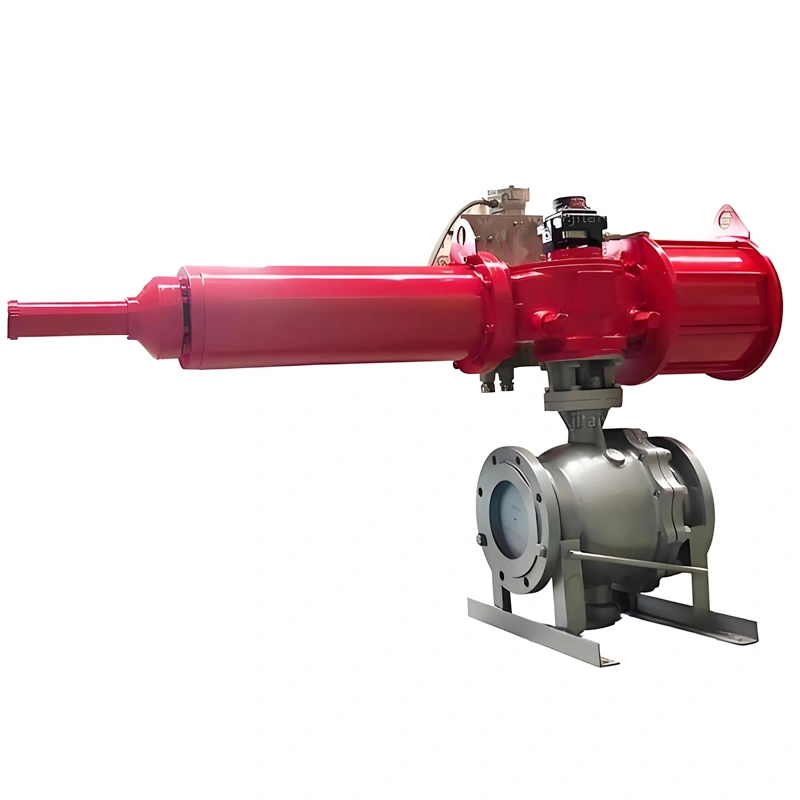
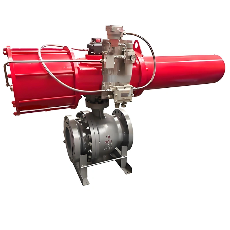
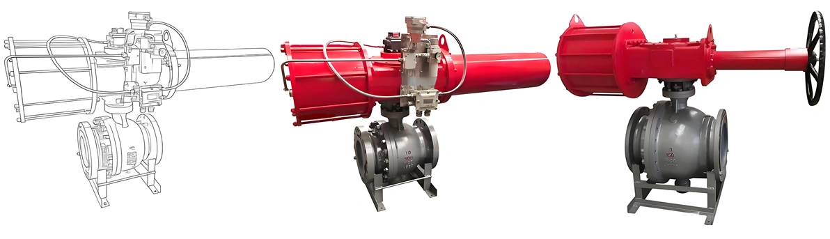
C. High-Performance Pneumatic Actuation: Precision & Reliability
The integrated pneumatic actuator delivers fast, consistent performance for automated fluid control. The double-acting design uses compressed air (4–8 bar) to both open and close the valve, ensuring reliable operation even in low-pressure air supply conditions. For emergency scenarios, the optional spring-return actuator automatically returns the valve to a fail-safe position (open or close) if air pressure is lost—an essential feature for applications such as chemical reactor feed lines, where uncontrolled flow could lead to catastrophic failures.
The actuator’s modular design allows for easy integration with control systems, including PLCs and SCADA systems, via the optional 4–20mA positioner. This enables remote monitoring of the valve’s position and precise control of flow rates, reducing the need for on-site personnel and improving operational efficiency.
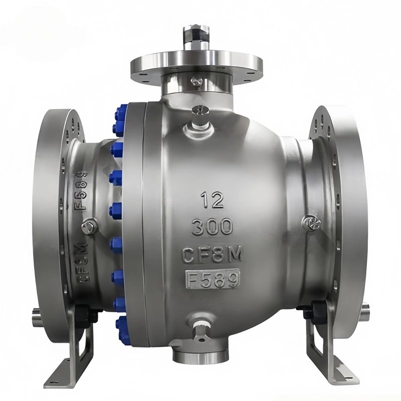
D. Corrosion-Resistant Material Combination: Longevity in Aggressive Media
The pairing of WCB carbon steel body and SS316 ball is carefully selected to balance durability and corrosion resistance. The WCB body provides the strength required to withstand 150LB pressure, while the epoxy coating protects against external rust and chemical exposure. The SS316 ball, with its molybdenum content, resists corrosion from saltwater, acidic solutions, and sulfur-containing media—common in offshore oil and gas applications.
In tests conducted in a coastal chemical plant, the SS316 ball showed no signs of pitting or corrosion after three years of service with seawater cooling systems, outperforming SS304 alternatives which typically require replacement after 18–24 months. This material synergy extends the valve’s service life to 8–10 years in typical industrial environments, reducing replacement costs and maintenance frequency.
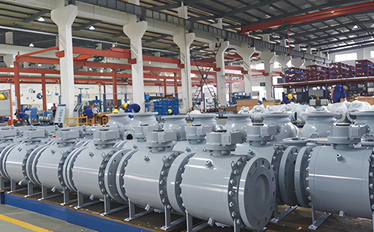
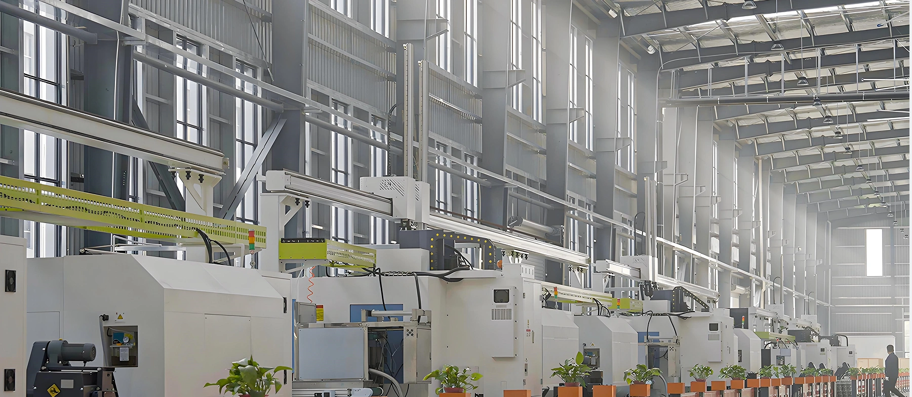
IV. Manufacturing Process
A. Raw Material Inspection & Preparation
Quality control begins with strict inspection of raw materials to ensure compliance with ASTM standards. WCB carbon steel castings undergo spectral analysis to verify chemical composition (ensuring carbon content between 0.25–0.35%) and ultrasonic testing (UT) to detect internal defects such as cracks or inclusions. SS316 bar stock for balls and stems is tested for chromium, nickel, and molybdenum content using X-ray fluorescence (XRF) spectroscopy, with material test reports (MTRs) provided for each batch.
Sealing materials, including reinforced PTFE and graphite, are subjected to hardness testing (Shore D 55–65 for PTFE) and thermal stability tests to confirm performance within the -29℃ to 200℃ temperature range. Fire-safe components are pre-tested in a controlled laboratory environment to ensure compliance with API 607 requirements before assembly.
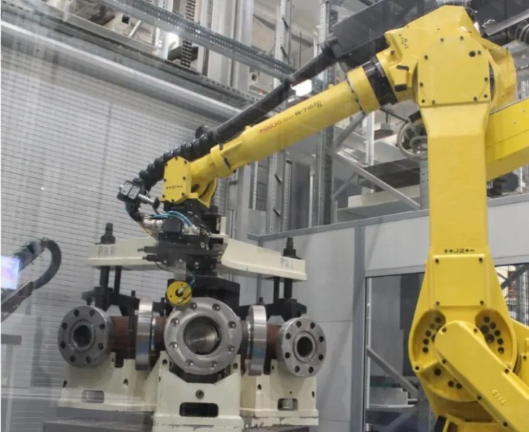
B. Valve Body & Ball Fabrication
The WCB body casting is first subjected to shot blasting to remove surface impurities, then machined using 5-axis CNC machines to achieve precise dimensional tolerances. Flange faces are machined to ASME B16.5 specifications, with a roughness of Ra 12.5–25μm to ensure proper gasket seating. The side-entry port and stem bore are honed to a smooth finish (Ra ≤0.8μm) to minimize friction between the stem and packing.
The SS316 ball is precision-machined from bar stock using a CNC turning center, followed by grinding to achieve a spherical tolerance of ≤0.01mm. The ball’s bore is drilled and polished to match the valve’s full-bore design, ensuring minimal flow restriction. After machining, the ball undergoes passivation treatment (nitric acid solution) to enhance corrosion resistance by removing free iron from the surface.
C. Assembly of Fire-Safe & Actuation Systems
Assembly is performed in a cleanroom environment to prevent contamination of sealing surfaces. The stem is first fitted with graphite packing rings (arranged in a V-shape for optimal sealing) and inserted into the body, followed by the SS316 ball, which is secured to the stem via a keyway connection. The reinforced PTFE seat rings are then installed, with a preload applied to ensure initial bubble-tight sealing.
The pneumatic actuator is mounted to the valve via an ISO 5211 flange, with laser alignment to ensure the actuator’s drive shaft is coaxial with the valve stem (runout ≤0.05mm). This alignment prevents premature wear and ensures smooth actuation. Limit switches and positioners (if specified) are calibrated to provide accurate position feedback, with testing conducted to verify that the valve opens and closes within the specified timeframes.
D. Quality Testing & Certification
Every TIANYU valve undergoes a rigorous multi-stage testing process before leaving the factory:
-
Hydrostatic Test: Conducted per API 598—shell test at 3.0MPa (1.5×150LB) for 5 minutes, with no leakage or structural deformation; seat test at 2.2MPa (1.1×150LB) for 3 minutes, with leakage measured below ANSI/FCI Class VI limits.
-
Fire Test: Random samples from each production batch undergo API 607 fire testing, including 30 minutes of exposure to high temperature and a subsequent leakage test to confirm fire-safe performance.
-
Operational Test: 100 cycles of open-close operation to verify actuation consistency, torque requirements, and position accuracy. Automated valves are tested with simulated control signals to ensure proper integration with control systems.
-
Non-Destructive Testing (NDT): Liquid penetrant testing (PT) of flange welds and body castings to detect surface defects; magnetic particle testing (MPI) of the stem to ensure structural integrity.
Upon successful completion of testing, each valve is labeled with a unique serial number, and a comprehensive test report is generated, including MTRs, test results, and certification documents.